
I've developed 2 methods for manual shutter control on Polaroid pack film cameras: A resistor array using a 12 point switch, and an Arduino controlling the power to the camera. Surprisingly, both cost around the same amount, and both retain the circuit board in the camera as well as automatic exposure as an option. The resistor array may be a bit easier to build, and it can be configured as an accessory which plugs in though it may be more difficult to modify the lens body to make it work. It is also more analog, meaning it's a knob with clicks between the shutter speeds. Here are the features of each method:
Arduino | Resistor Array |
|---|---|
shutter speeds in 1/3 stop increments (programmable) | shutter speeds in 1 stop increments only |
shutter speeds 2 sec - 1/1500 (lower end programmable) plus bulb | shutter speeds 1 sec - 1/1000 plus bulb |
fits in battery compartment, dongle not an option at present | dial protrudes from battery compartment or can be installed in a dongle |
switchable between auto and manual shutter | switchable between auto and manual with either a switch, or by plugging in the dongle |
shutter speed not affected by the scene selector switch | shutter speed 2 stops slower on "sunny day only" setting |
shutter circuit modified by desoldering shutter timing switch and soldering 2 leads | shutter circuit modified by removing electric eye and tapping into one side (more difficult) |
shutter speed selected by push button switches and/or rotary encoder | shutter speed selected with 12 point switch only |
very accurate shutter speeds measured by arduino | shutter speeds determined by resistance and the analog shutter circuit which may need calibration |
Cost: around $10 | Cost: around $10 |
The Arduino method may be easier to modify the shutter circuit (just 2 solder points), but requires a computer to program the arduino as well as more soldering and a 3D printed battery compartment to hold it all. It's also more digital, meaning it has an oLED display and buttons to change the shutter speed, though a knob can be used. It requires the following parts:
Instructions for this conversion were orginally posted at Polaroid Shutter Control on Github.
While the arduino is controlling the Polaroid shutter, the Polaroid shutter circuit is connected to ground, which discharges the internal capacitors and keeps the shutter open. This effectively puts the camera into "bulb" mode. The arduino de-energizes the Polaroid shutter circuit and is waiting for the shutter to be cocked (sensed by the shutter timing switch closing) at which point, the arduino energizes the Polaroid camera circuit by turning on the opto-isolator and effectively connecting battery power to the Polaroid. Having said this, no power is being used by the Polaroid ciruit until the shutter is pressed. When the shutter is pressed, a switch energizes the solenoid which holds back the second shutter curtain and opens the first shutter curtain, also opening the shutter timing switch. Once the arduino detects the shutter open (timing switch open), it times the exposure, then cuts off power to the camera, de-energizing the solendoid and closing the shutter.
These steps are for building the rotary encoder version of the shutter circuit, which uses the rotary encoder version of the battery door 3D file. If you want to use the button switches to select the shutter speed, connect the 2 switches to D3 and D4 and use the button version of the battery door.
The hinge will need to be glued to the battery compartment body. This is because it's difficult to print the hinge on the body with the correct orientation. File down the top printed surface of the hinge and the battery compartment indent where the hinge will go. This will rough up the surface so the glue will stick. | 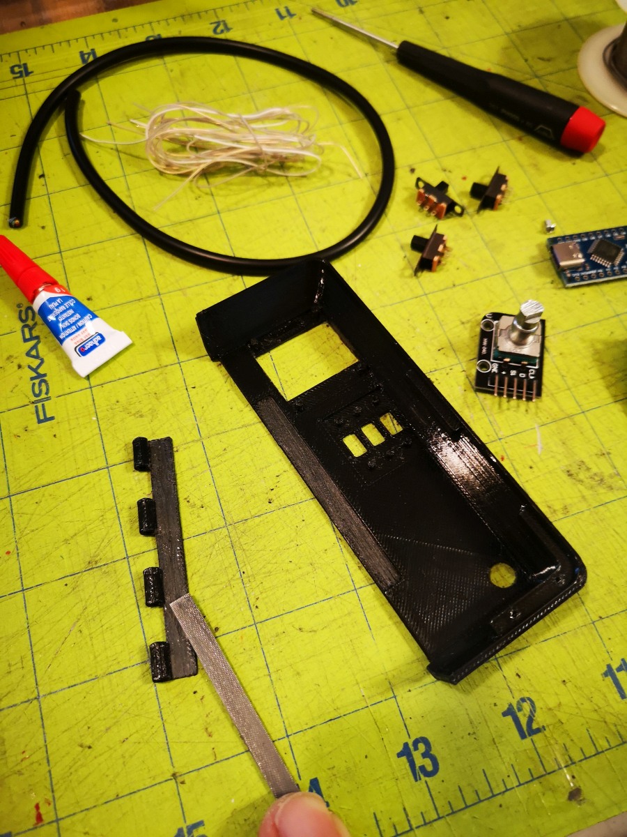
|
Apply glue to the indent in the battery compartment where the hinge will mount. | 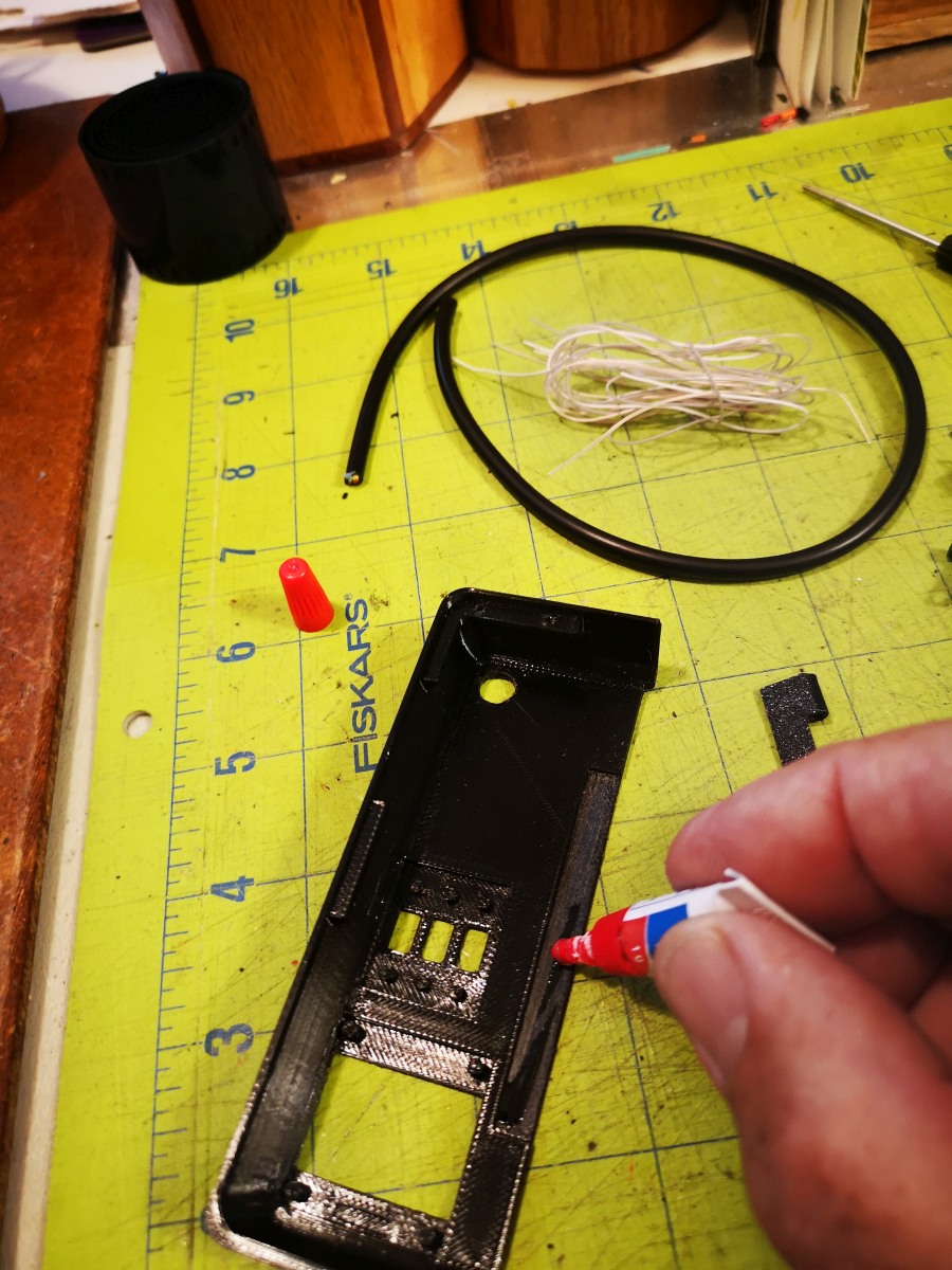
|
Mount the hinge and clamp in place until the glue is dry. | 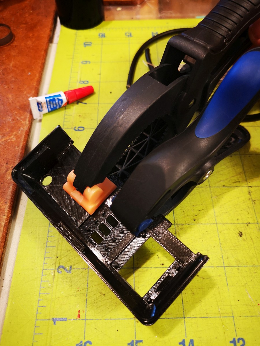
|
File down the soldered leads at the top of the SSD1306 oLED display so they will fit into the indent at the top where the oLED screen mounts in the battery compartment. Alternatively, you can desolder the pins if this is easier. | 
|
File the battery compartment where the oLED display mounts to fit the display, testing its fit as you file it down. Be sure the glass part of the display clears the edges. | 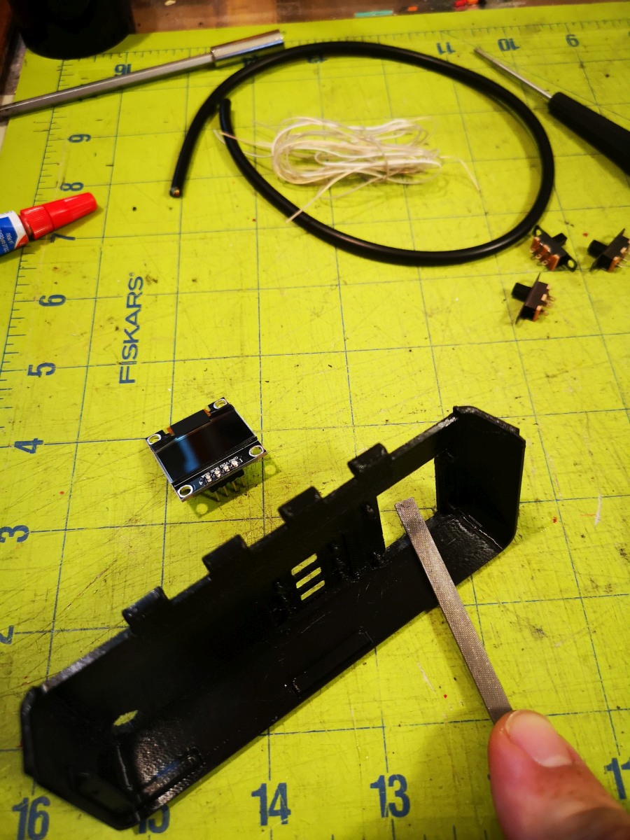
|
Clip around 1/2 of the leads of of the back side of the oLED display. Skip this step if you desoldered them. This will make the leads less likely to confict with other components. | 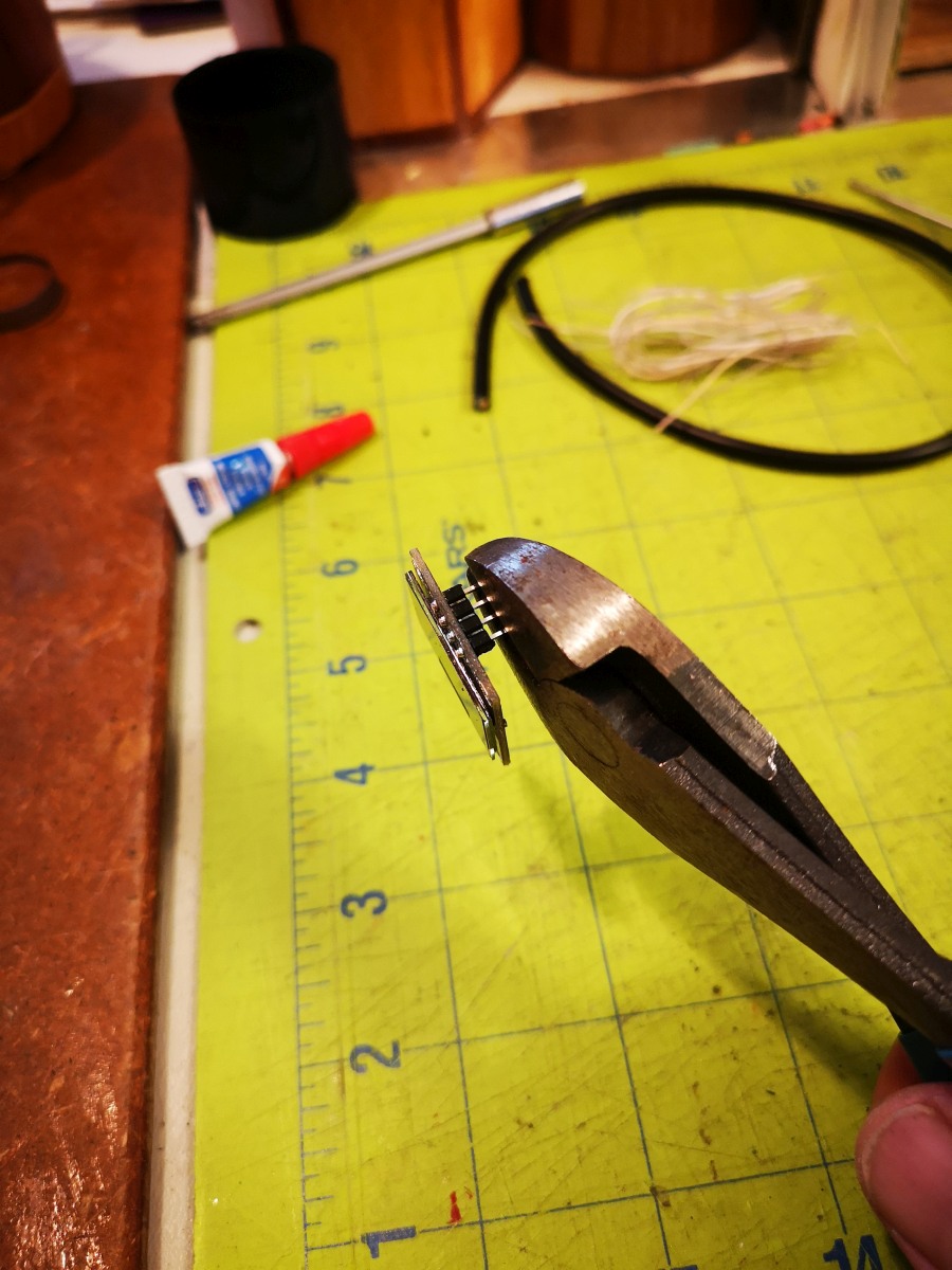
|
Mount the oLED display into the battery compartment, being careful not to crack the screen. The plastic posts should protrude above the circuit board. | 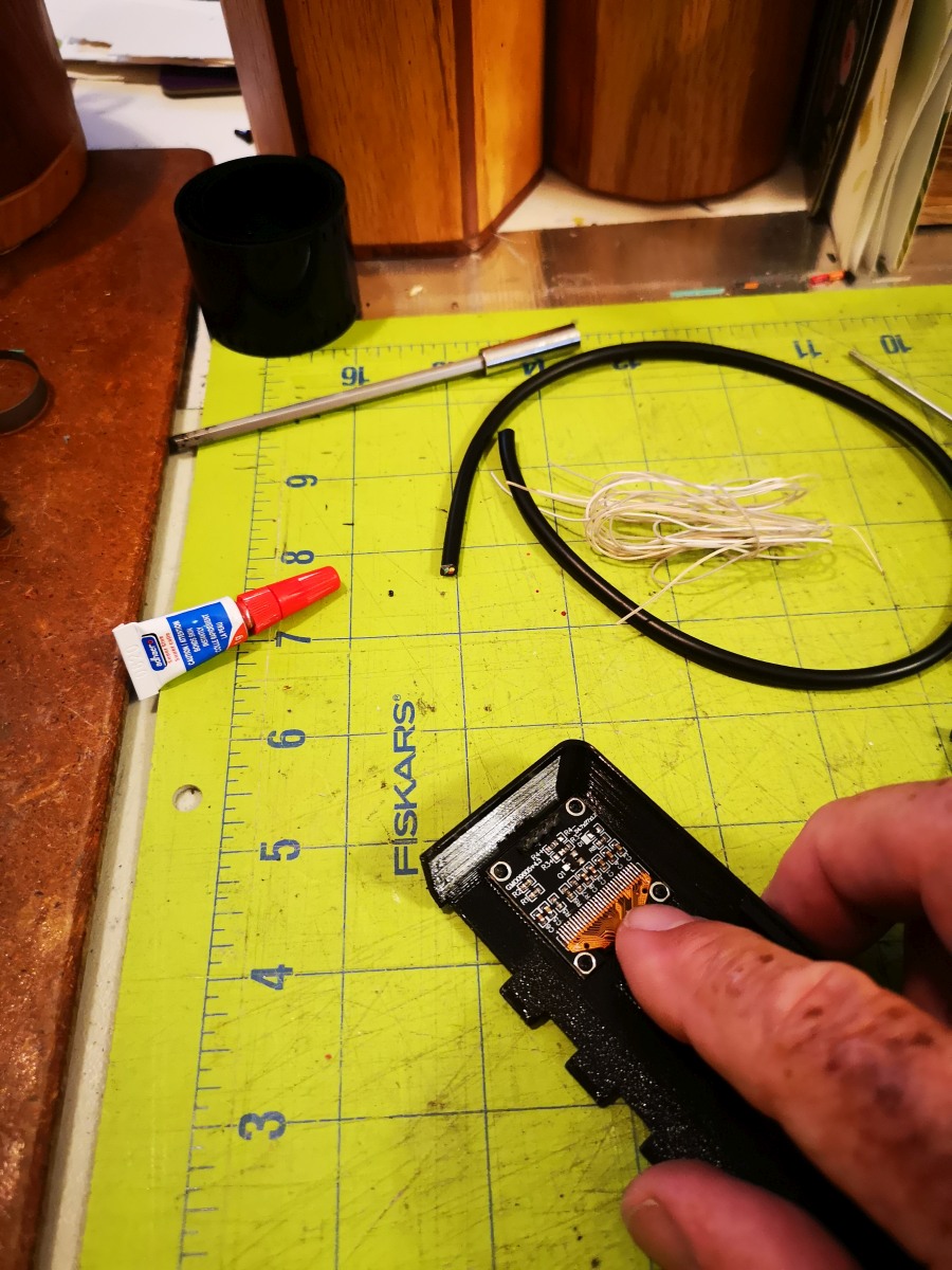
|
Heat up a steel rod with a torch sufficiently to melt the pastic material used to 3D print the battery compartment. PETG will require a higher temperature than PLA. Don't heat it too hot or the plastic will get burnt. | 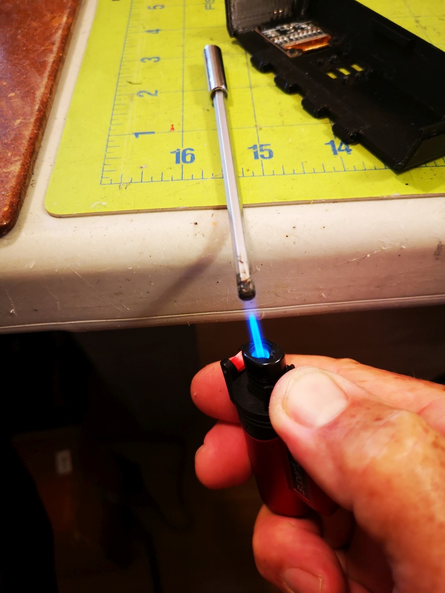
|
Press down on each plastic post to melt the plastic so it squishes against the board, enough to secure it to the battery compartment. You may have to reheat the rod to keep the heat sufficient. | 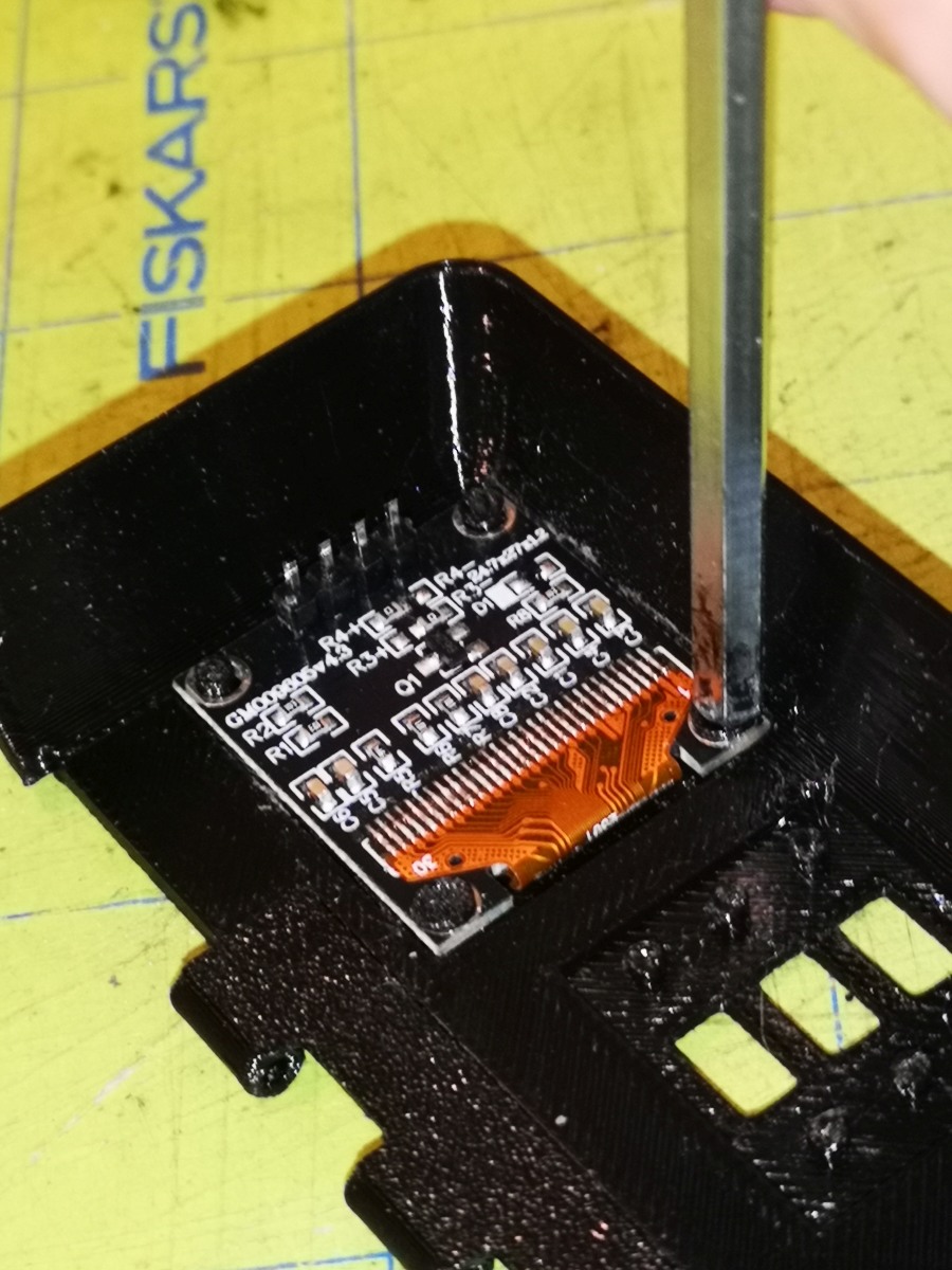
|
Mount the 3 SPST switches into the battery compartment. It's easiest if the battery compartment is supported on both ends so the switches can sit inside their slots fully for the next step. | 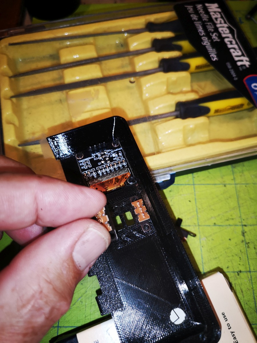
|
Melt the plastic posts against the switches to secure them in place. | 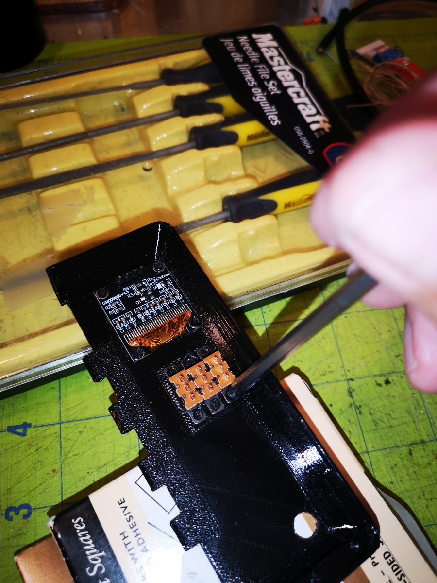
|
File the top right corner (when viewed upside down, pins down) of the rotary encoder so that it fits into the battery compartment, testing its fit while filing. | 
|
Mount the rotary encoder, ensuring the shaft sticks through the hole, and secure it in place with a small screw. | 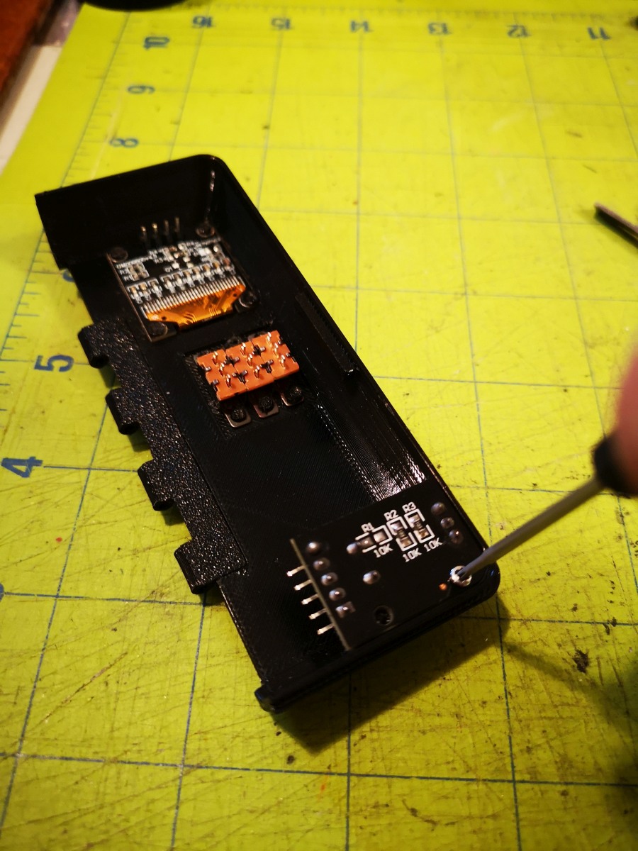
|
Cut or file off the end of the rotary encoder shaft until around 3mm of the shaft protrudes from the top surface of the battery compartment. The rotary encoder knob should sit flush against the battery compartment. | 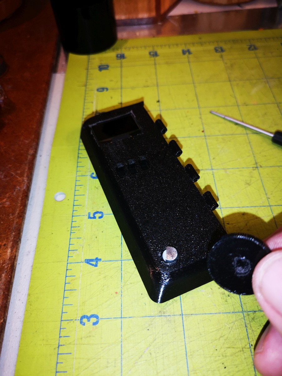
|
Fit the knob onto the rotary encoder shaft. It will be a tight fit, and may require some filing to get it to mount. | 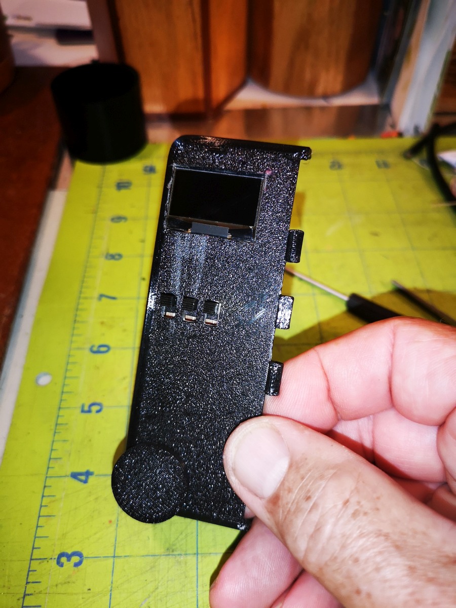
|
Plug the arduino nano into a USB cord and connect it to a computer that has Arduino IDE installed. | 
|
Upload the program found here by copying and pasting the code into an Arduino IDE session. Complete instructions for this process can be found here. | 
|
Solder leads to the 3.3v, A4, A5, 5v, GND, D7, D8, D9, and D11 of the Arduino nano. | 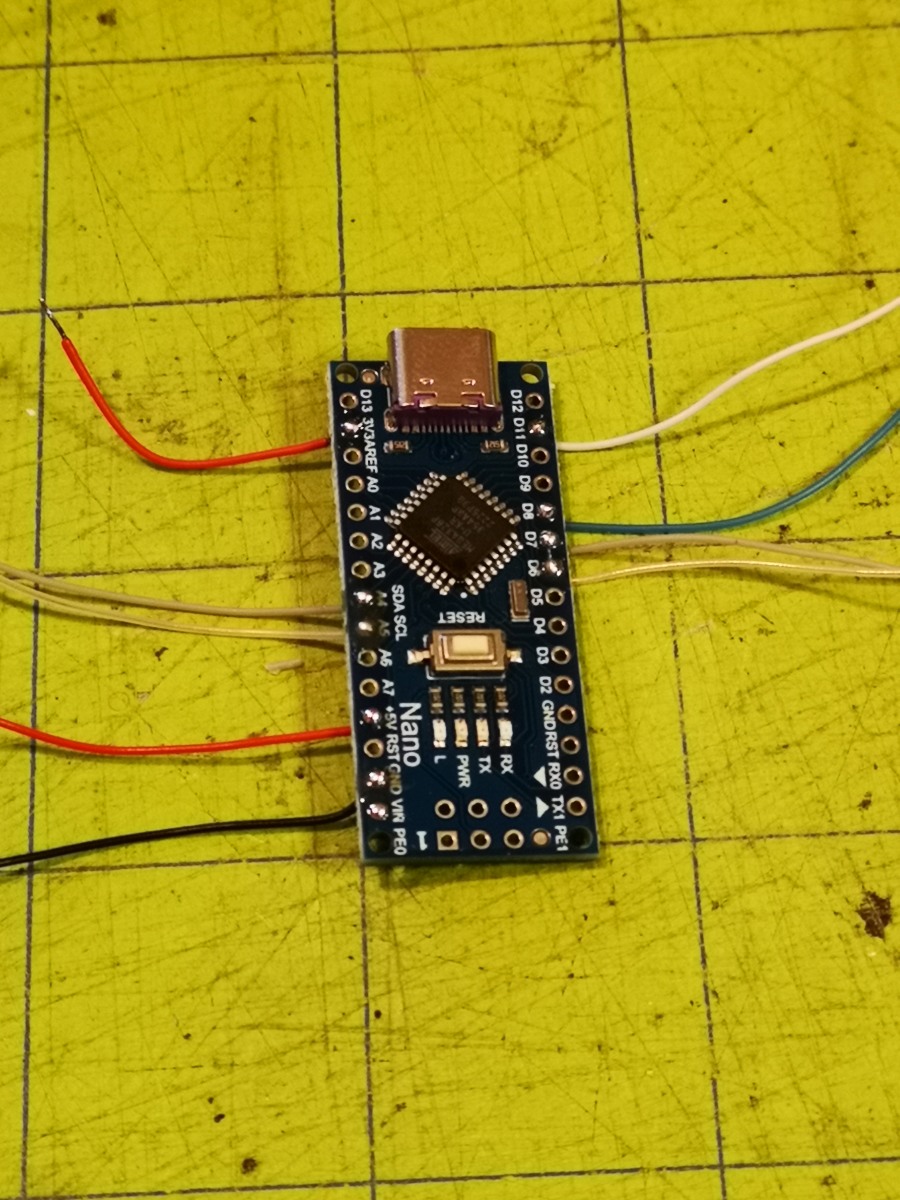
|
Solder a 330 Ohm resistor to the anode (pin 1 under the dot) of the TLP127 opto isolator. It's easiest to tin the contacts then join them together by a short touch of a solder iron. Solder a black lead to the cathode (pin 3, to the right of the anode on the same end). | 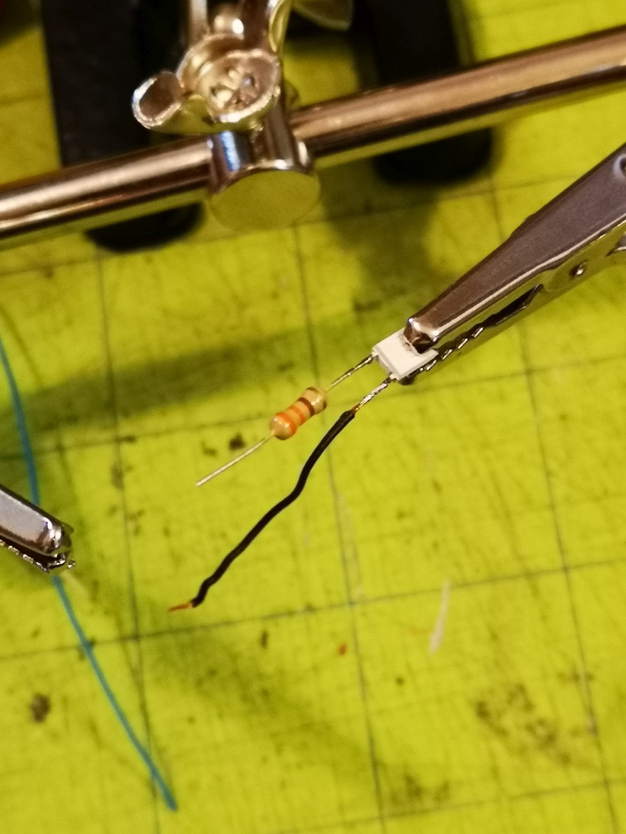
|
Place shrink wrap tubing over the cathode lead as well as a wider piece over the resistor and the TLP127. This will help prevent flexing from breaking the pins off the TLP127. | 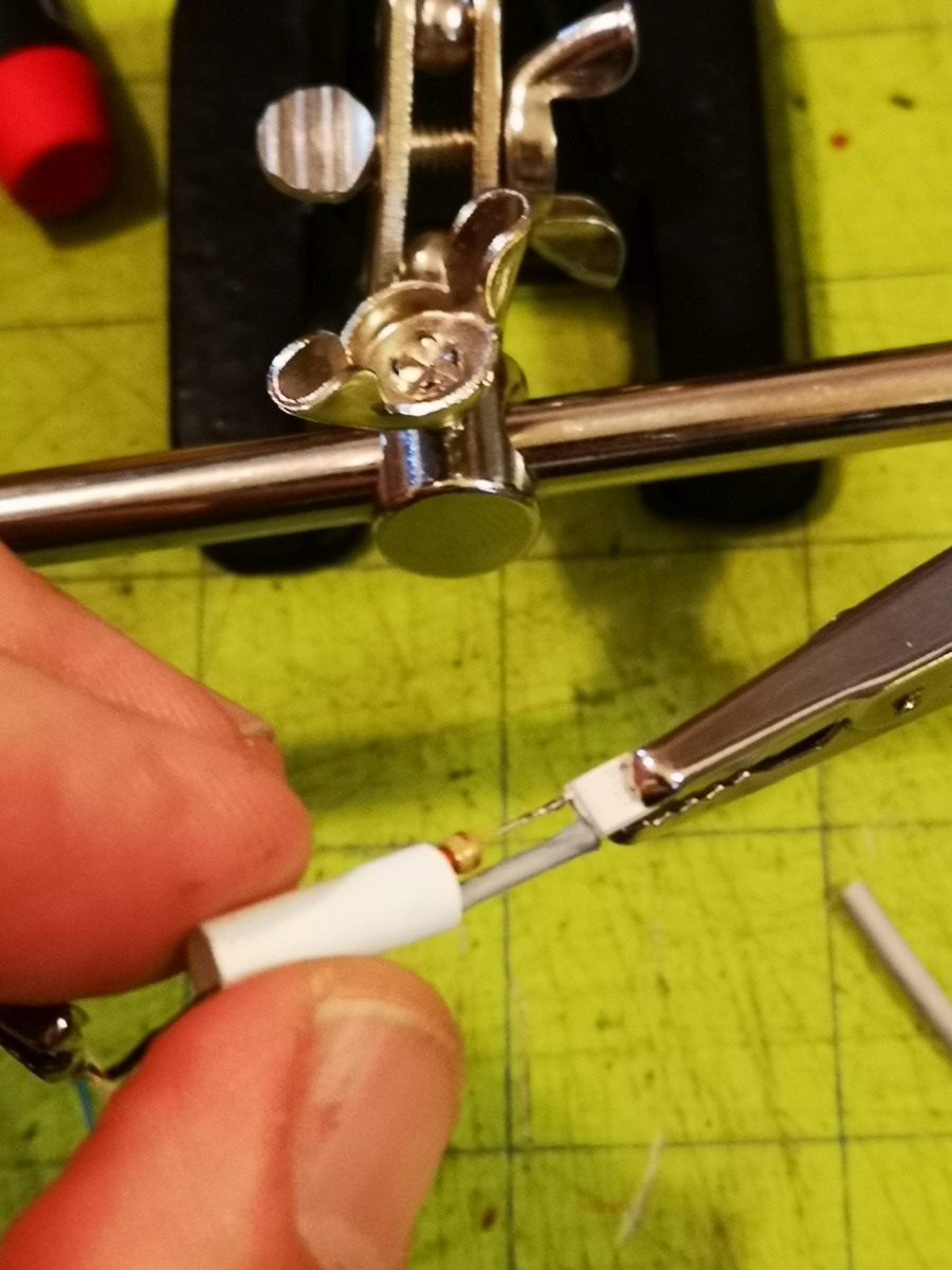
|
Use a small torch to shrink the tubing, being carefull not to overheat it. | 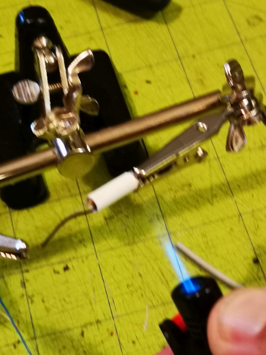
|
Solder leads to the collector (pin 6, opposite the anode or pin 1) and the emitter (pin 4, opposite the cathode or pin 3). You will want to use distinctive wires for each of these connections as you will have to differentiate between them when connecting them to the rest of the circuit. | 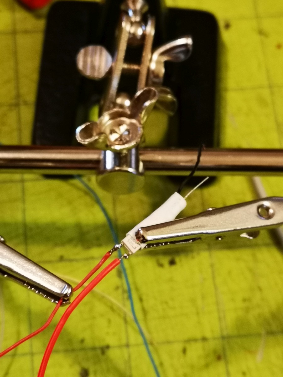
|
Slip shrink wrap tubing over the entire assembly to firm it up so it won't flex and break the contacts on the TLP127. | 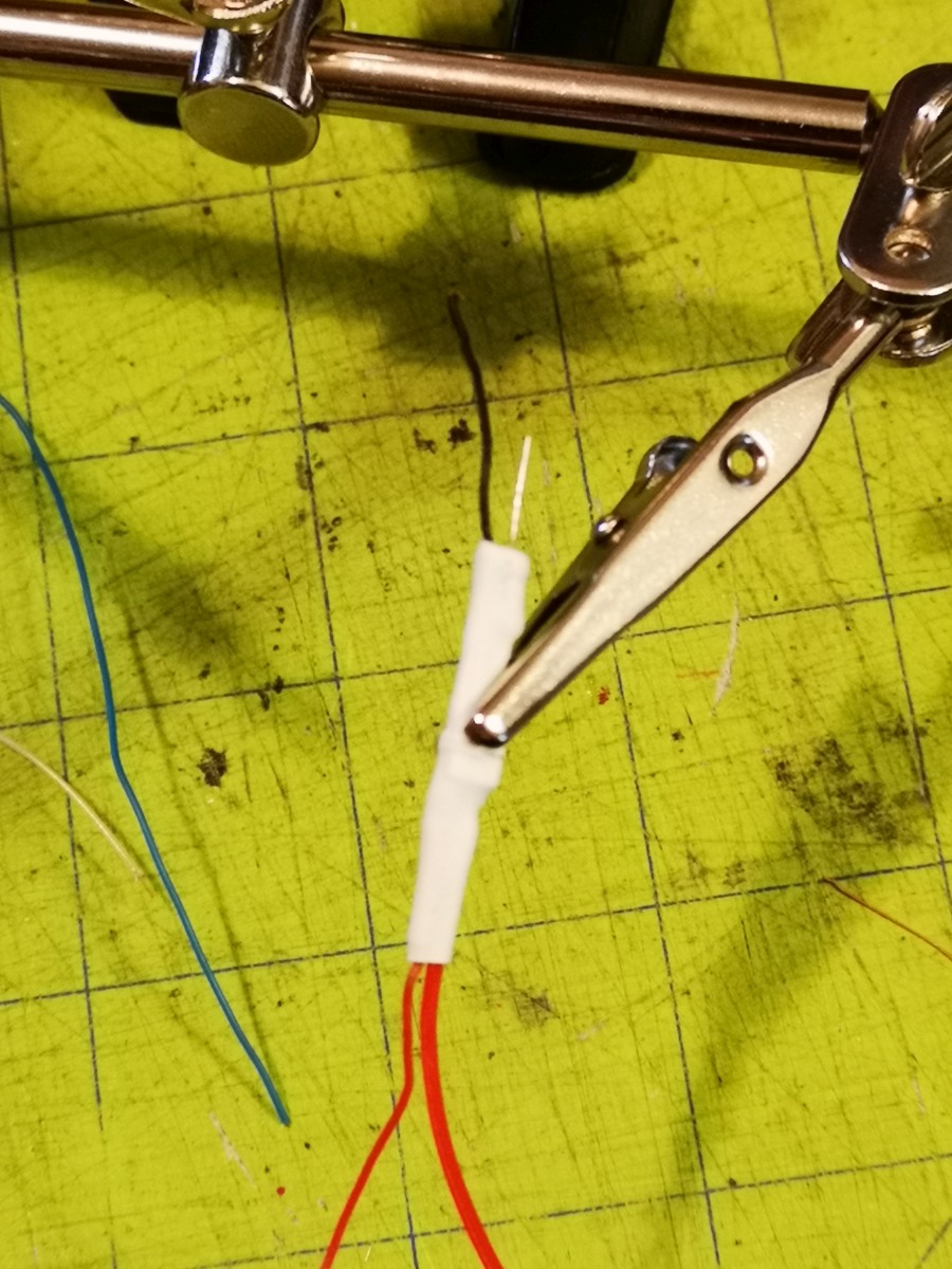
|
Place shrink wrap tubing over the resistor lead, put a right hand bend on the end of the lead, and solder it to the bottom side of pin 9 of the arduino nano and the cathode (black wire) to the GND terminal on the same side of the nano. Configure it so it sits parallel to the arduino nano. | 
|
Study this connection diagram and reference it to perform the next steps. Click on the thumbnail for a larger version to display and/or print. | 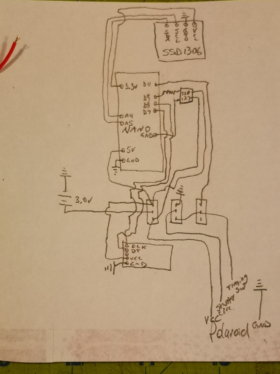
|
Solder a wire between the bottom terminal of the middle switch to the middle terminal of the right switch. | 
|
Solder the leads from the arduino to the oLED display: A4 to SDA (left terminal), A5 to SLC (2nd from left), 3.3v to VCC (2nd from right), leaving GND disconnected for now. | 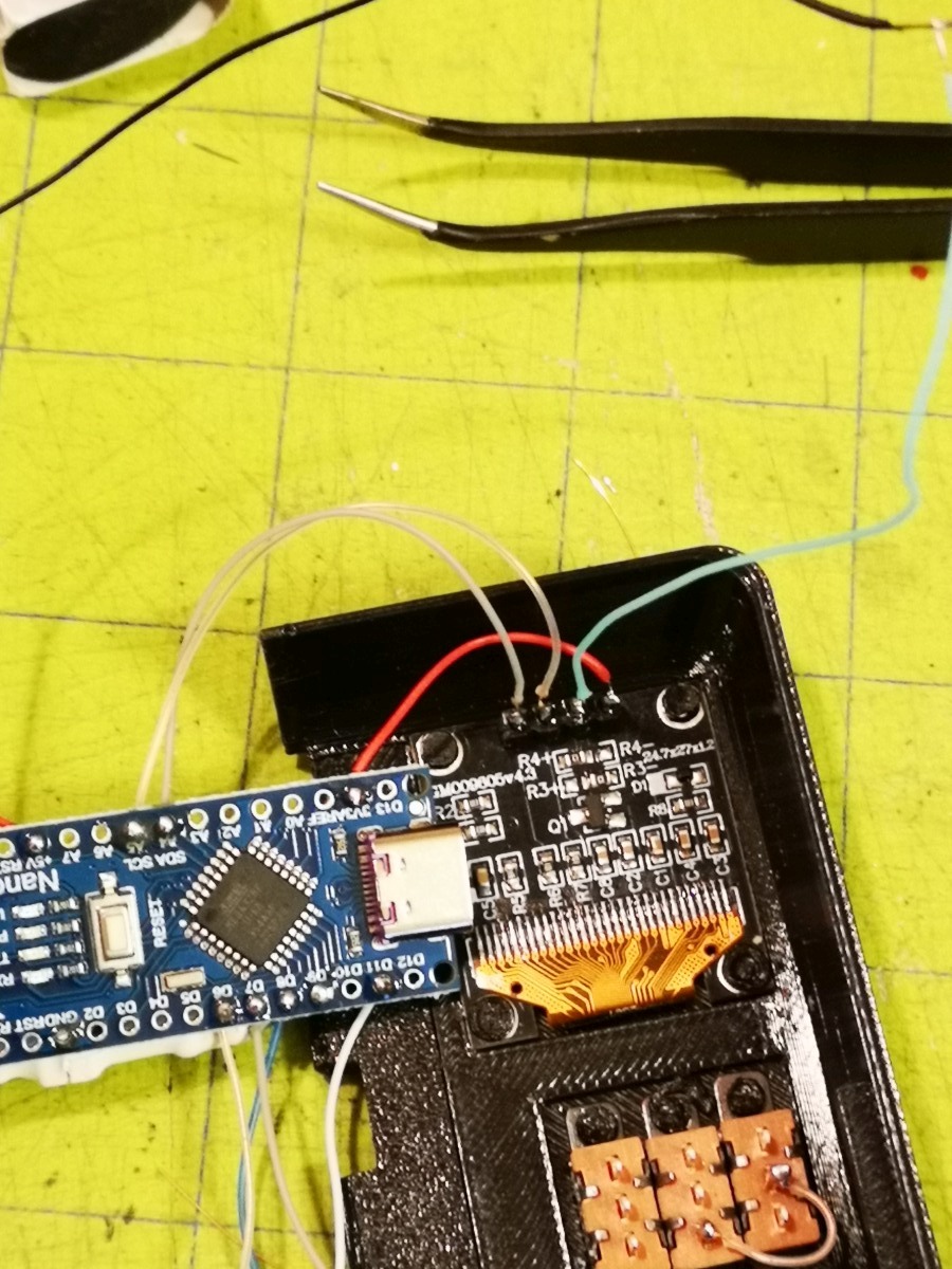
|
Connect the GND lead on the nano to the GND terminal lead on the oLED display and plug the arduino into a USB cable. The oLED display should power up with a shutter speed of 160. If it doesn't recheck all connetions going to the oLED display. Disconnect the GND leads. | 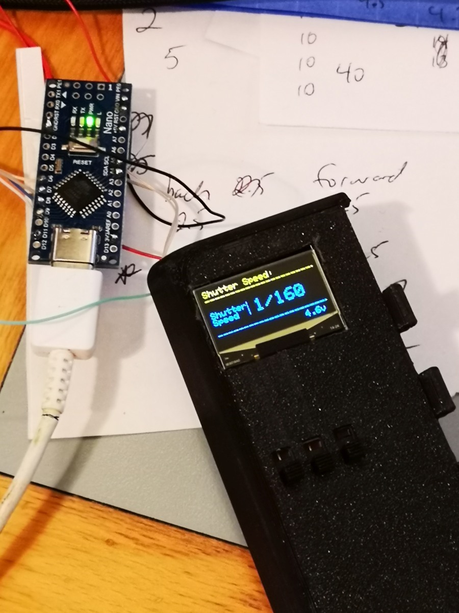
|
Solder the lead from D11 on the nano to the top terminal on the right switch. | 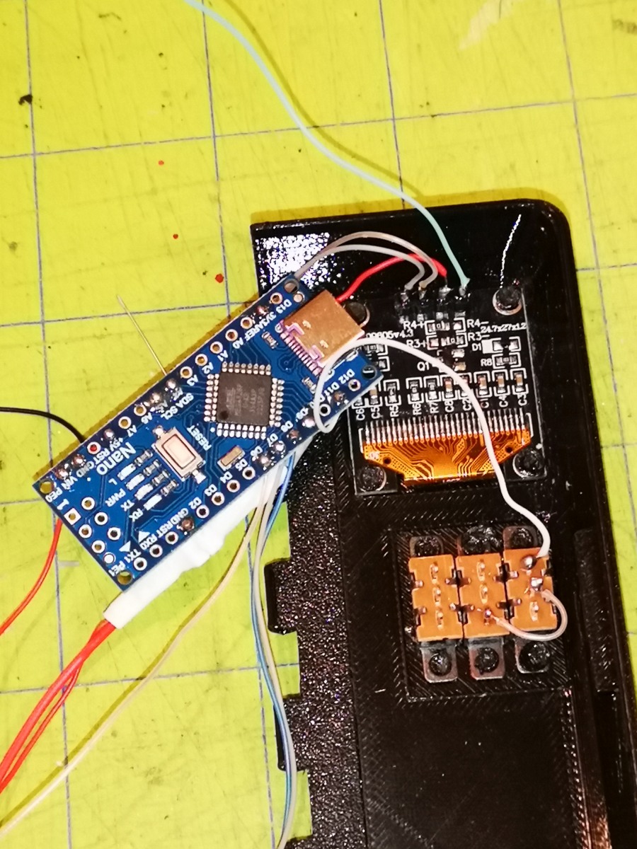
|
Solder the lead from D7 on the nano to the CLK terminal (top) on the rotary controller. Solder the lead from D8 on the nano to the DT terminal (2nd from top) on the rotary encoder. | 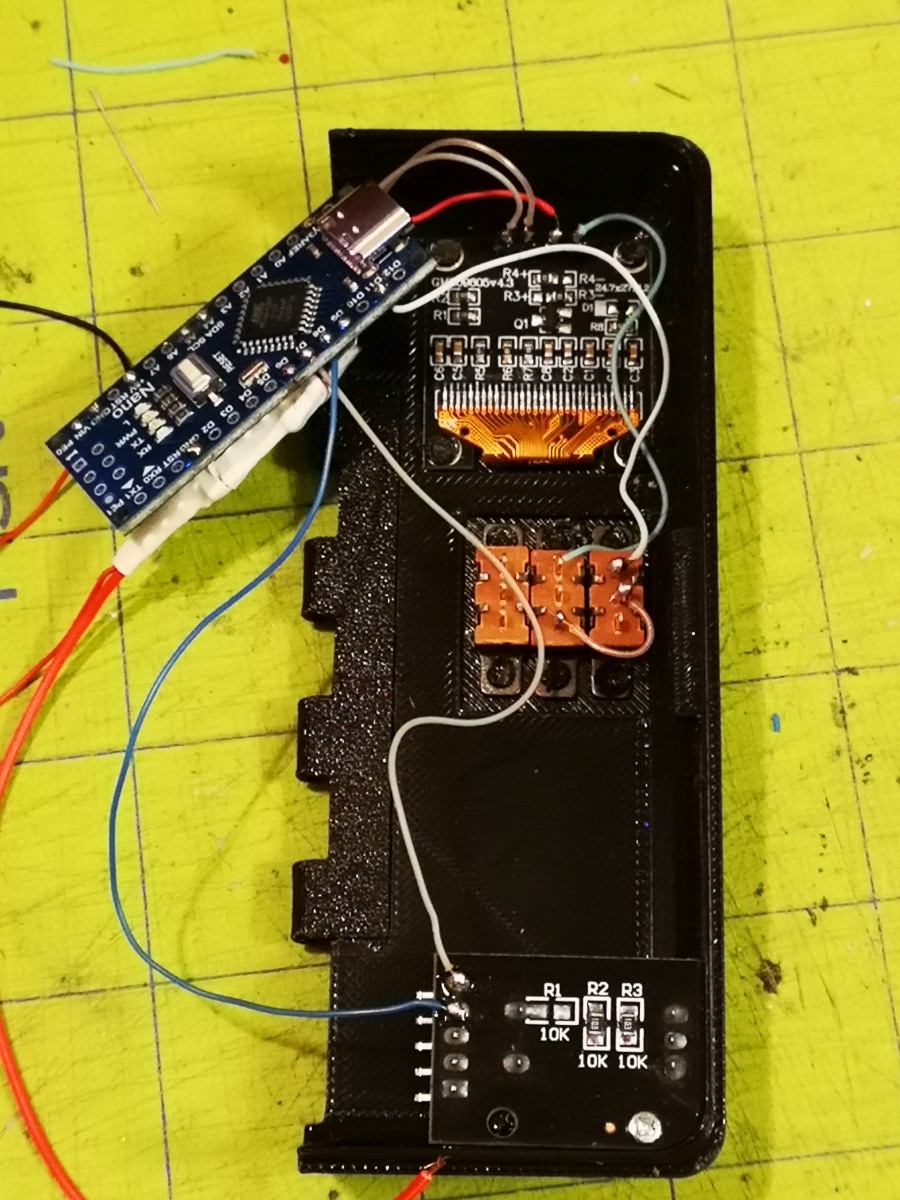
|
Solder the leads from 5v on the nano, 5v on the rotary encoder (2nd from bottom), and the collector pin (pin 6) on the TLP127 to the top terminal of the left switch. This will provide power for the arduino circuit and camera when in manual mode. Solder the lead from the emitter (pin 4) of the TLP127 to the bottom terminal of the left switch, along with another lead that will connect to the camera battery lead. | 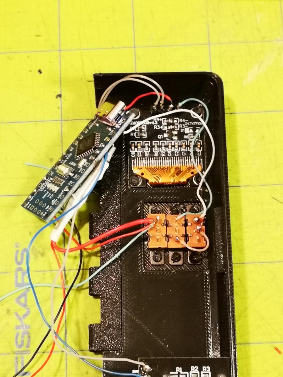
|
Attach the GND lead from the oLED display to the top terminal of the middle switch. Don't solder it yet. | 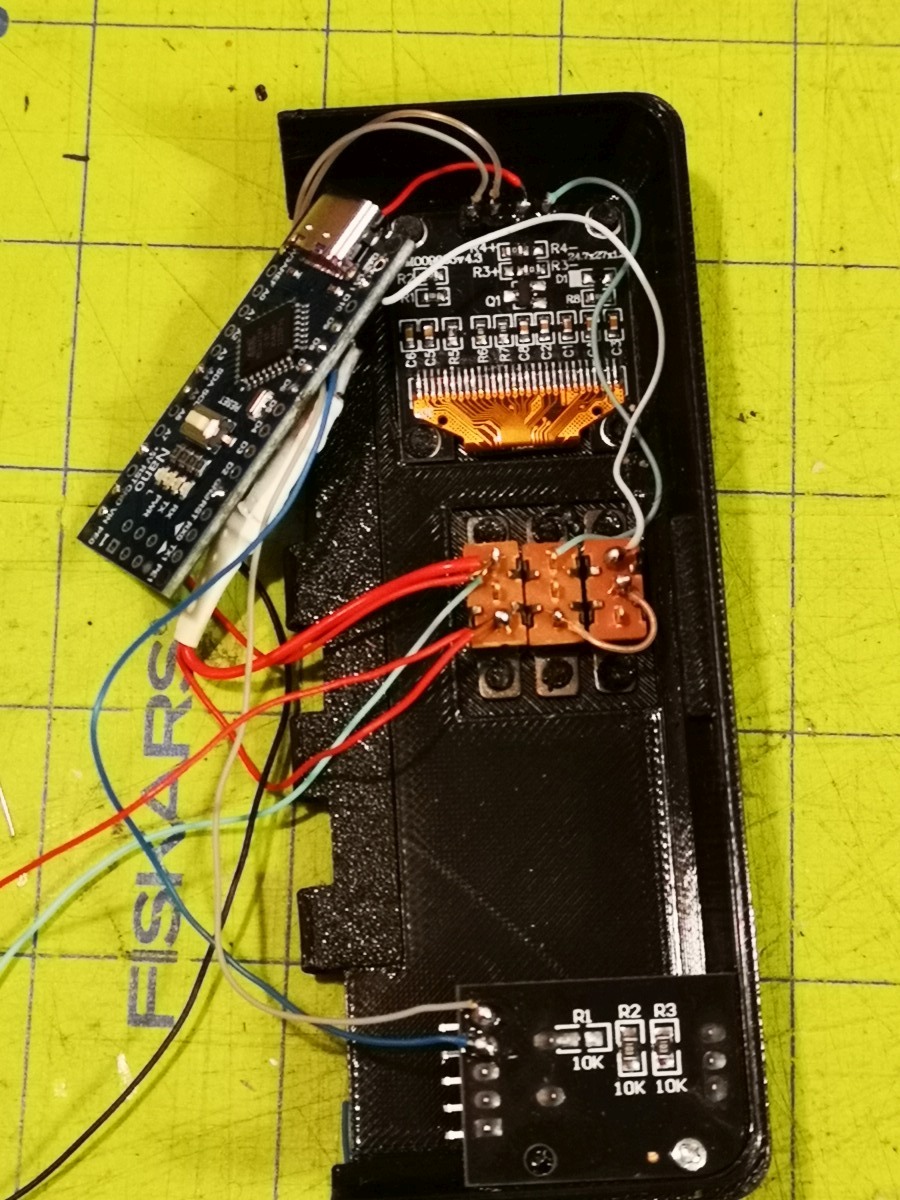
|
Solder the GND lead from the nano and the GND lead from the rotary encoder (bottom terminal--picture shows 2nd from bottom which is incorrect, refer to diagram) to the top terminal of the middle switch (along with GND to the oLED display). | 
|
Solder a red lead to the middle terminal of the left switch and connect it to a 3.0v power source. Attach the GND terminal on the rotary encoder to GND on the battery. | 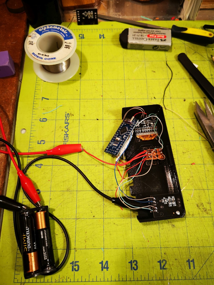
|
Flip the battery compartment over and flip the right switch up to turn it on. The display should turn on with a shutter speed of 160. | 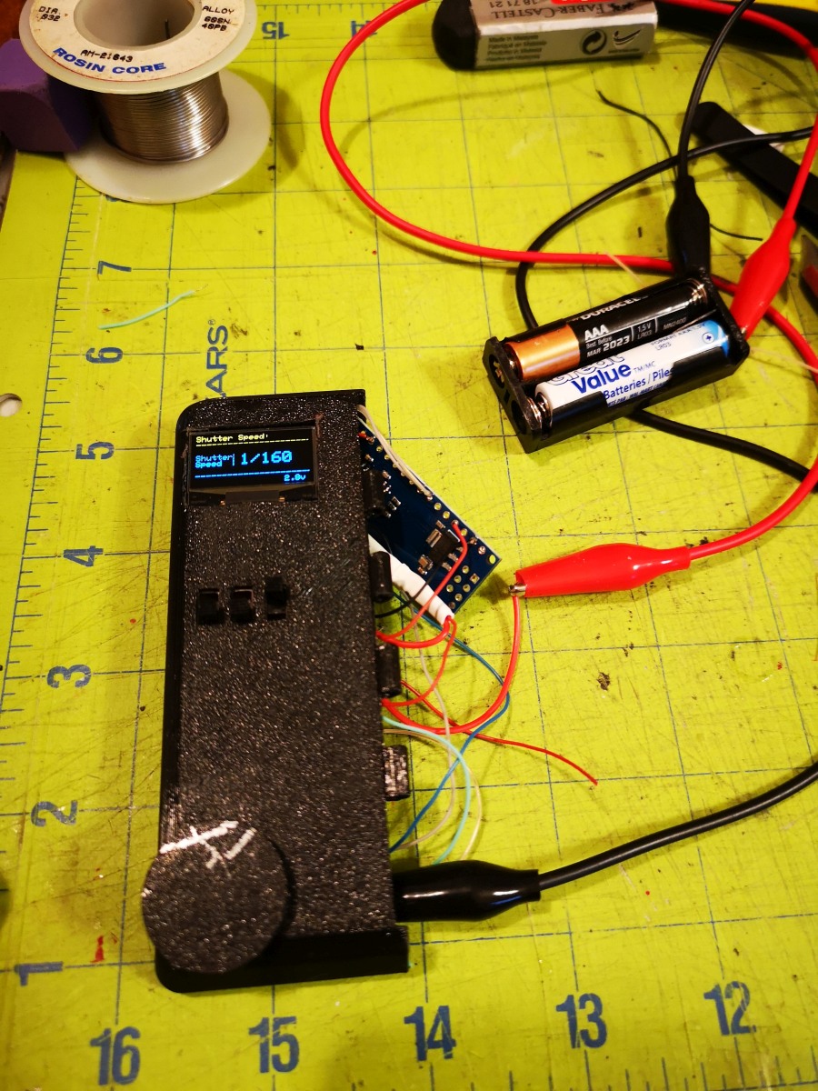
|
Spin the rotary encoder know to verify that it will change the shutter speed on the display. This module should be ready to connect to a camera. |
|
Remove the metal sticker at the top of the lens body and remove the three screws holding the lens body together. | 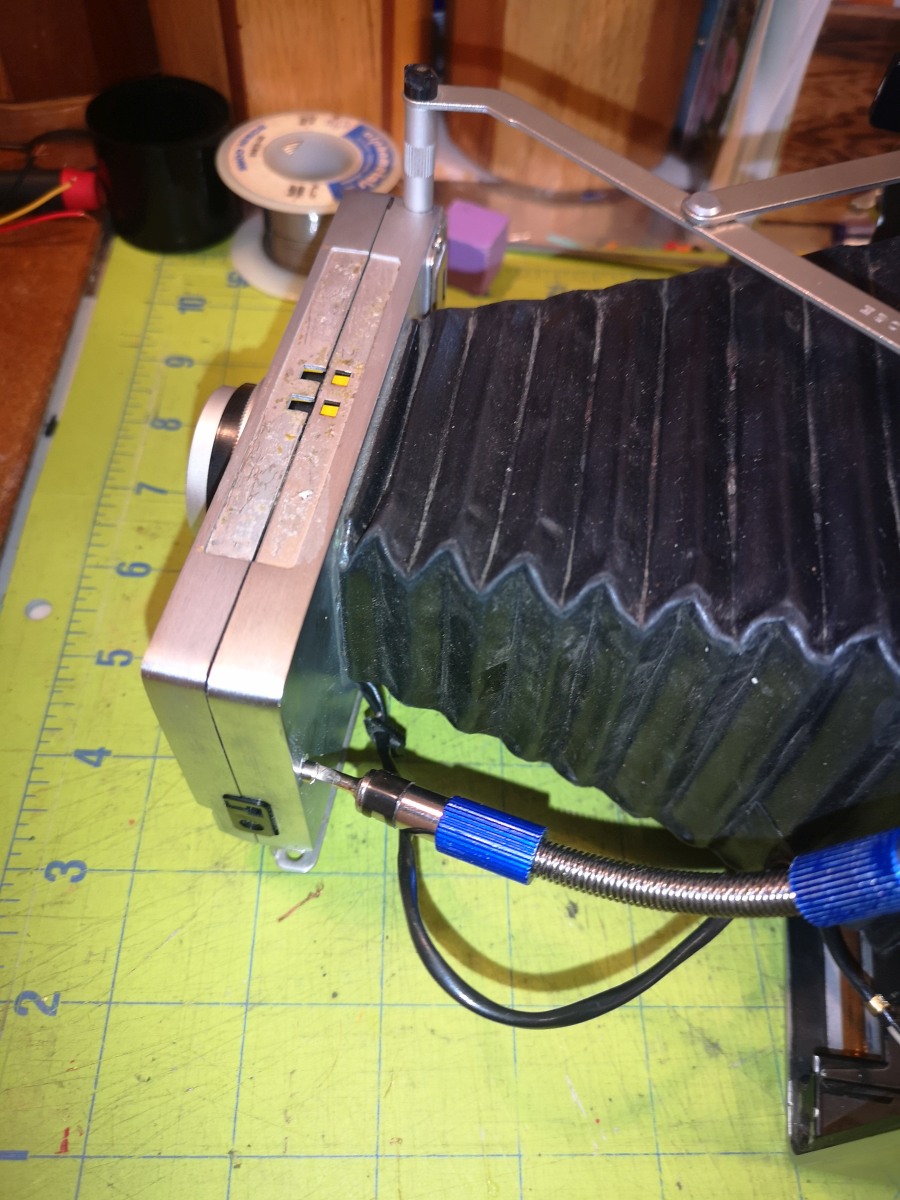
|
It's easiest to use a flexible shaft on the screwdriver. Don't remove the smaller screws holding the shutter cable. | 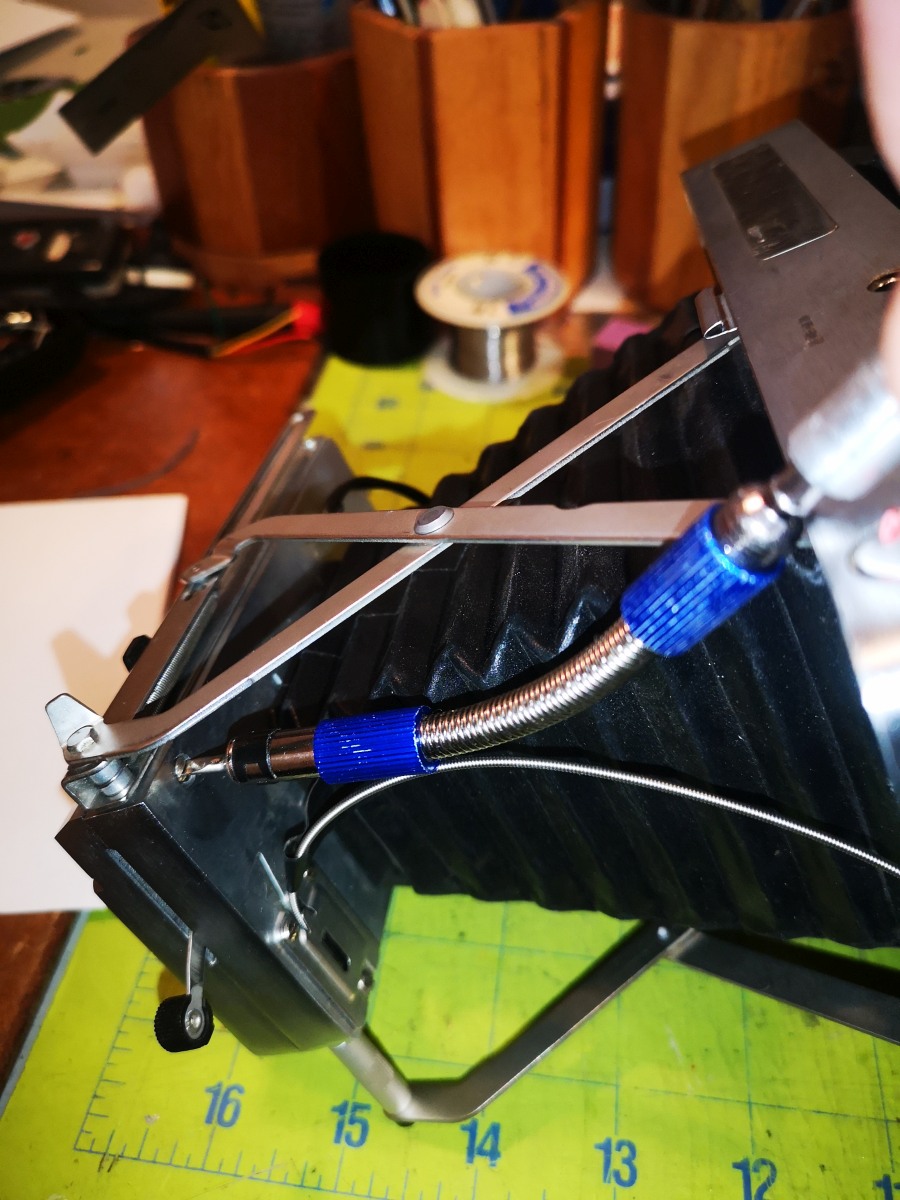
|
This screw is longer than the other two. | 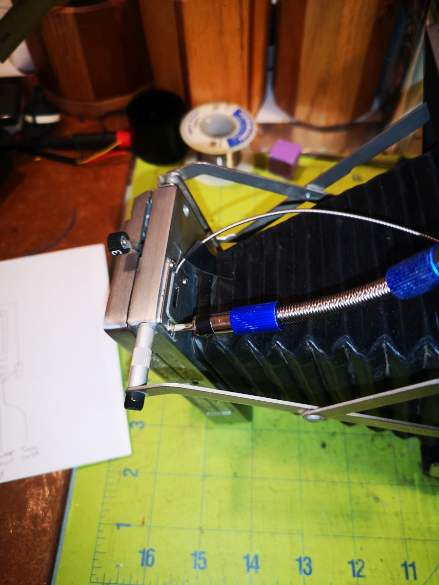
|
Open the shutter body from top to bottom. | 
|
Remove the light shield from the lower left corner of the lens body. | 
|
Remove the left hand screw from teh shutter body. | 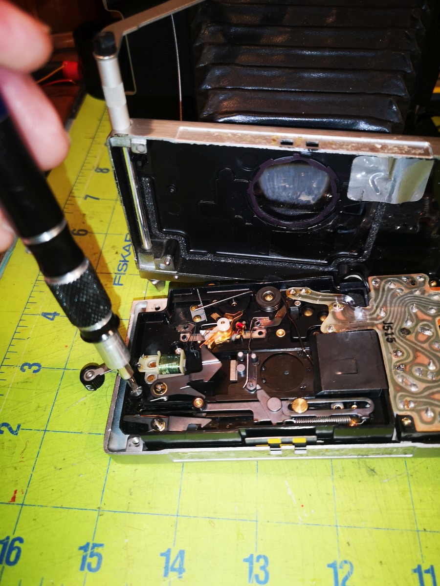
|
While pulling down the shutter cocking mechanism, remove the brass screw at the bottom right of the shutter body. | 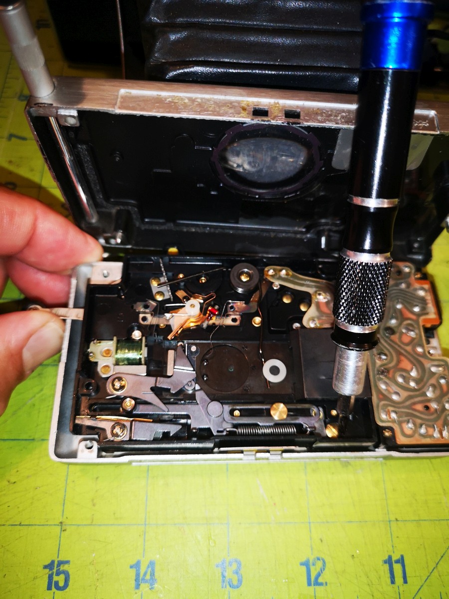
|
Remove the small lower left hand screw holding down the circuit board housing. | 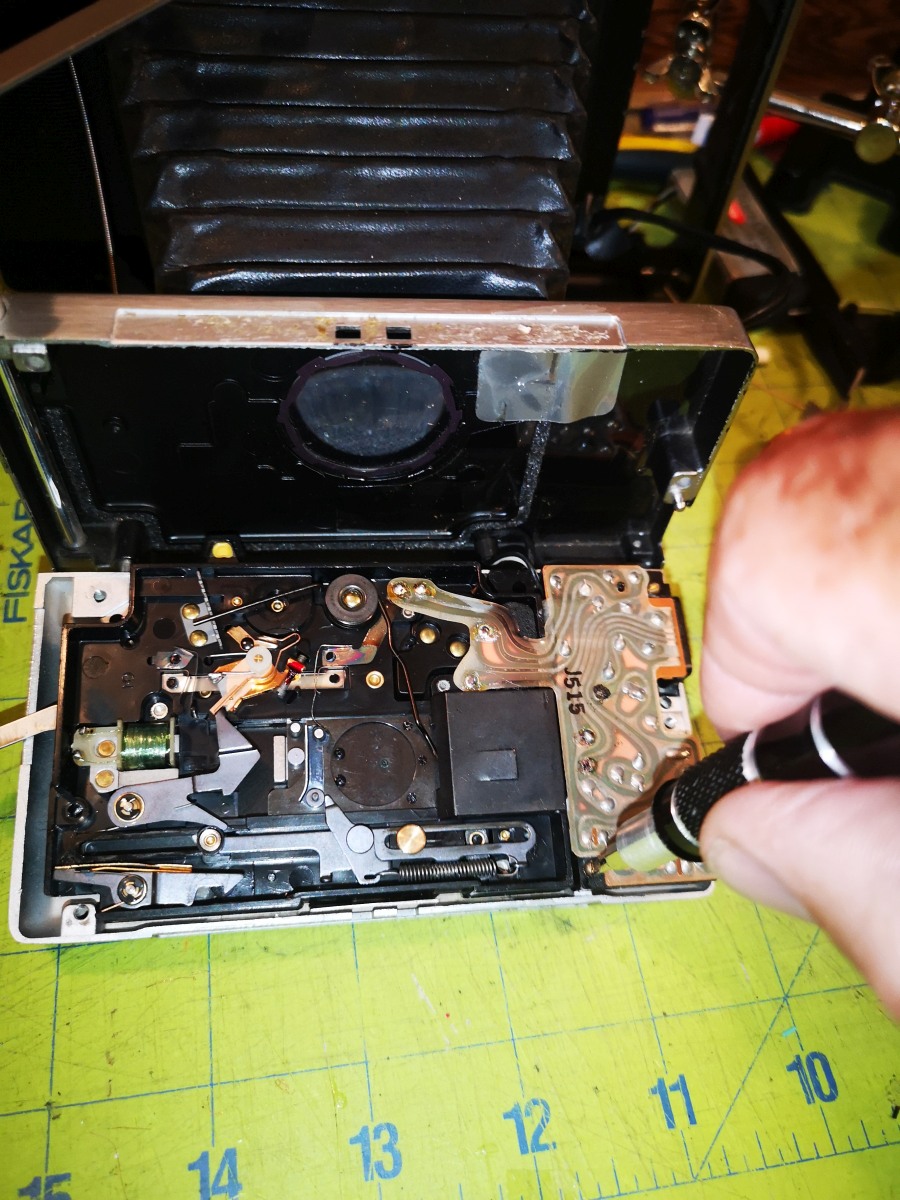
|
Remove the small upper right hand screw holding down the circuit board housing. | 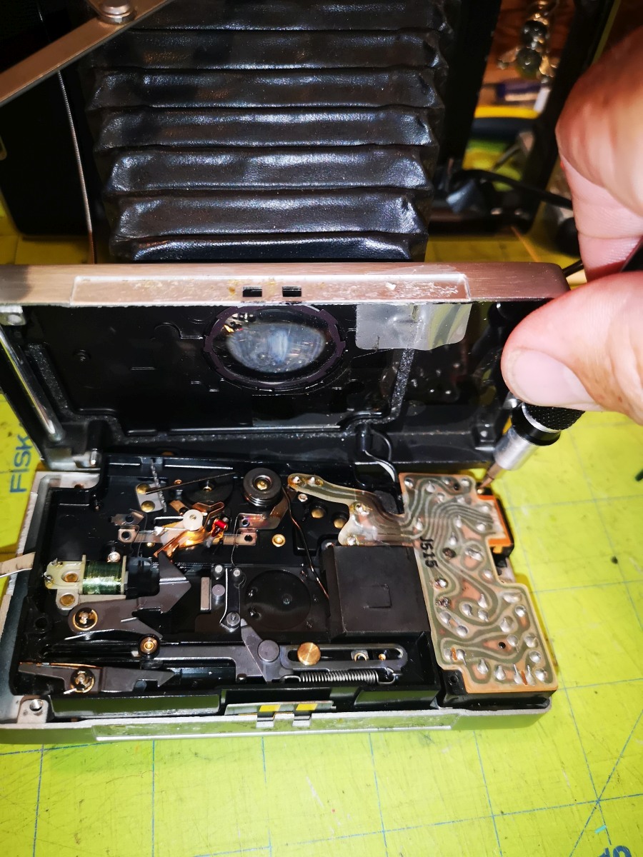
|
Flip the shutter body over. | 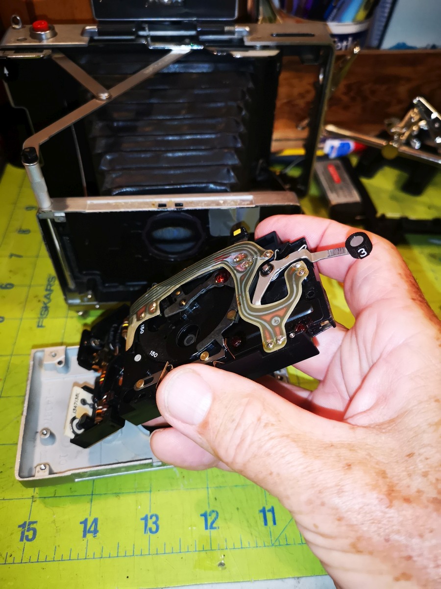
|
Cut the leads to the battery/power connector on the ribbon cable. | 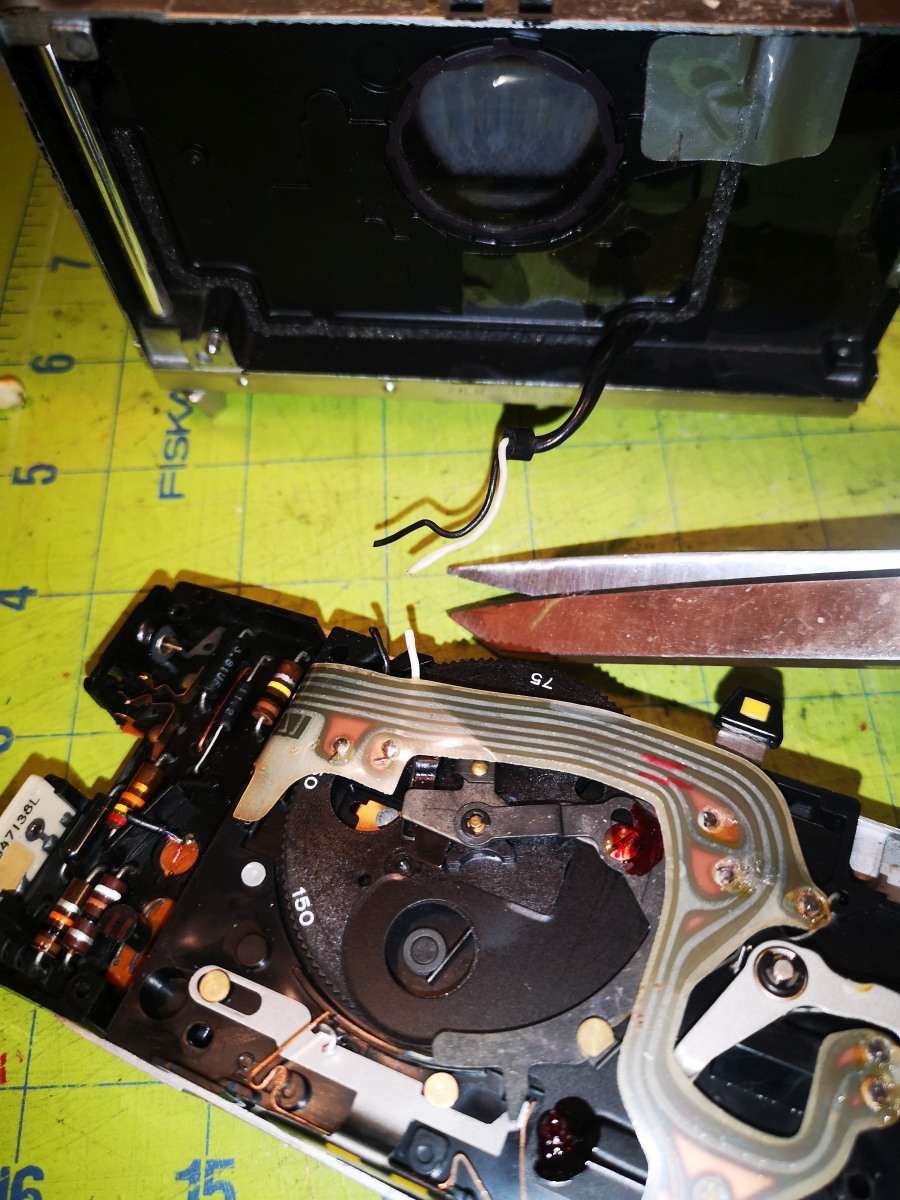
|
Desolder the contact connecting the shutter timing switch to the ribbon cable. You can either use a vacuum desoldering tool or you can lift the ribbon cable while melting the solder. Try to minimize the time heating the ribbon cable as it will melt and the copper trace it supports is very fragile. | 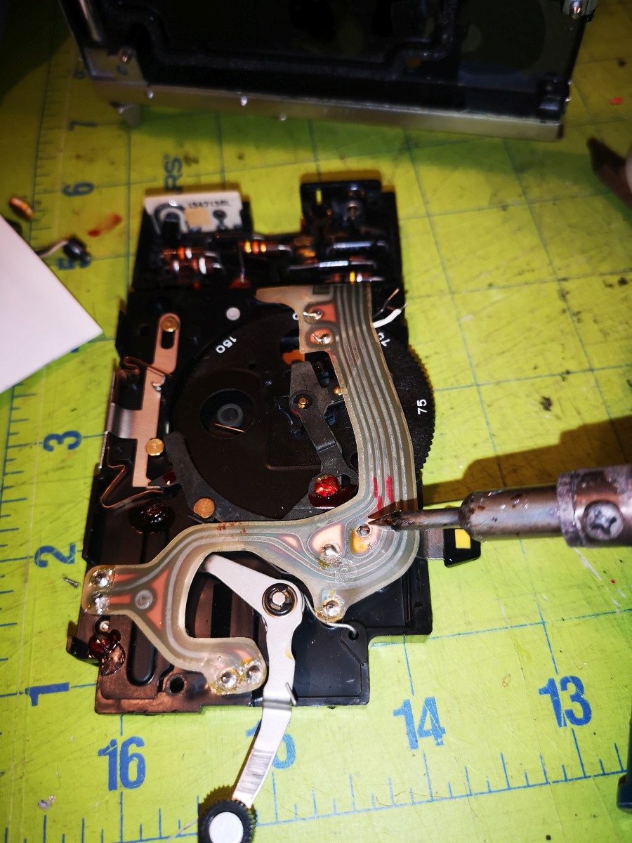
|
This is a delicate operation which even Polaroid technicians were not allowed to do! | 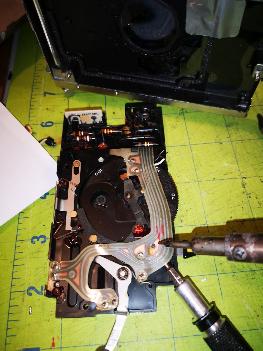
|
Carefully bend up the ribbon cable and secure it bent up with a piece of tape so you can do the next step. | 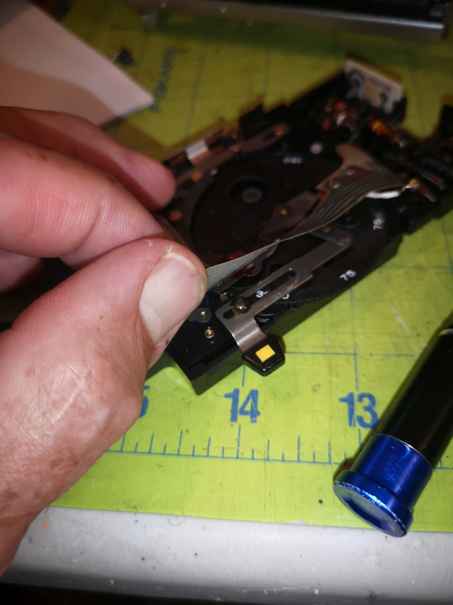
|
Solder a lead from a 4 conductor cable to the shutter timing switch. It's best to try bending down the tip of the switch contact so that it won't eventually poke through to the ribbon cable. Label this lead as the "shutter timing switch." | 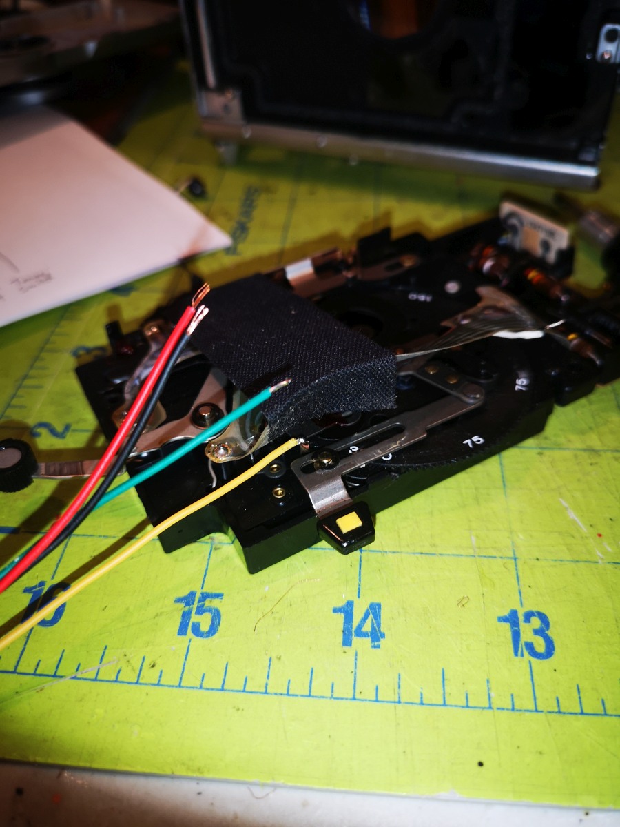
|
Place a piece (or 2) of electrican's tape under the ribbon cable where the timing switch contact was soldered to insulate it from the ribbon cable. | 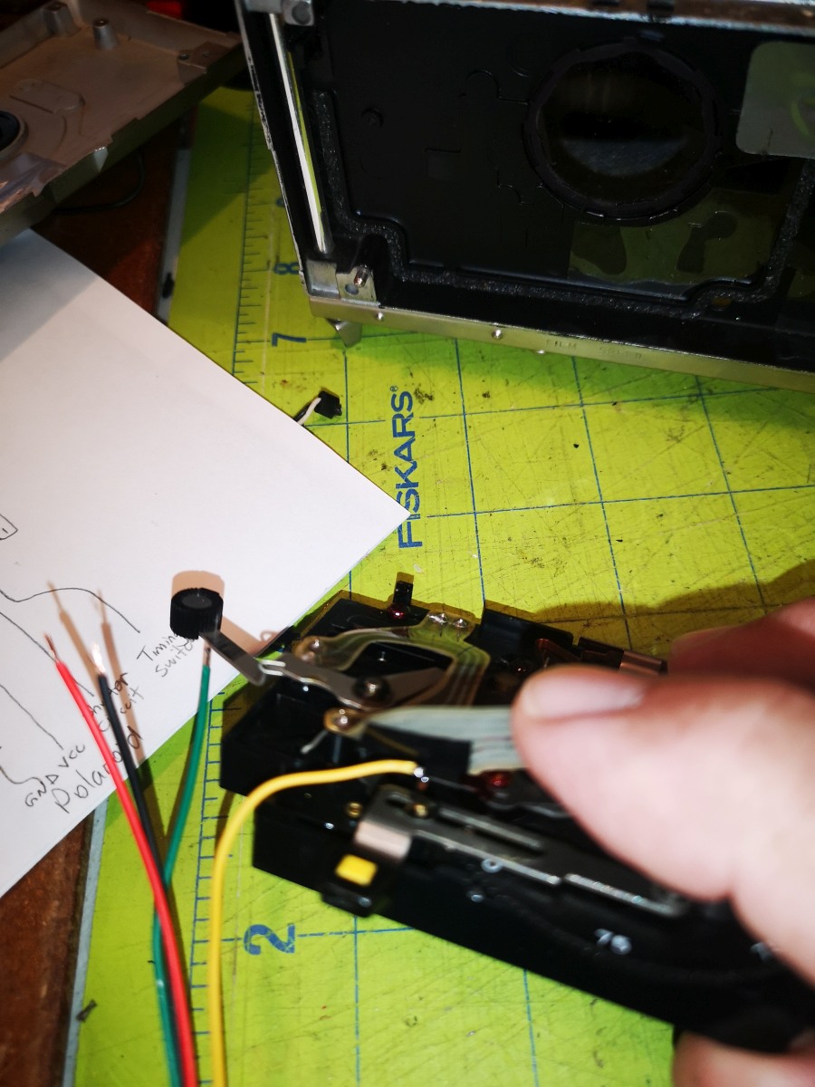
|
Solder a lead from the 4 conductor cable to the location where the shutter timing switch was soldered. Label/document this lead as the "shutter circuit". | 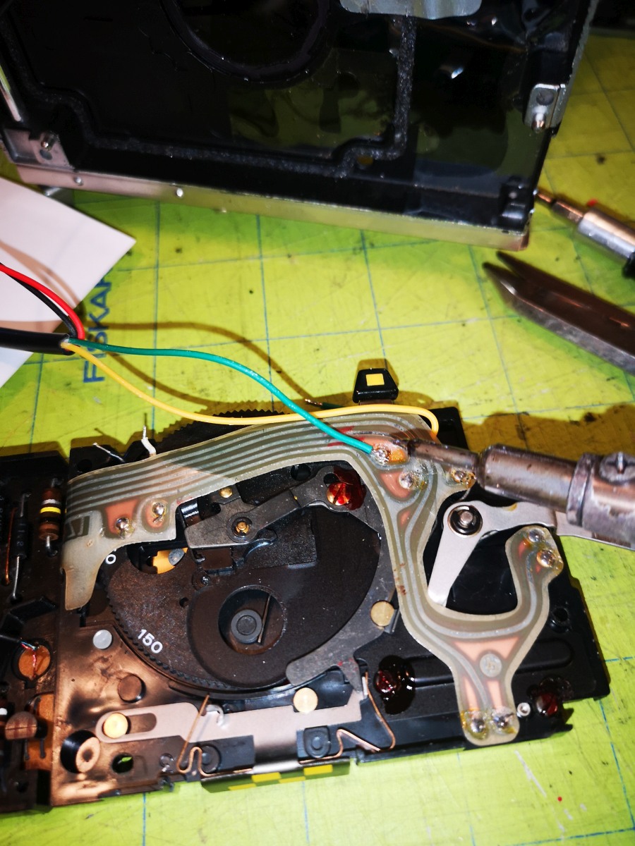
|
Put shrink wrap tubing over the red/black leads on the 4 conductor cable, then solder these leads to the power leads, being sure that the red lead on the cable is soldered to the white lead going to the ribbon cable, and the black leads are soldered to each other. | 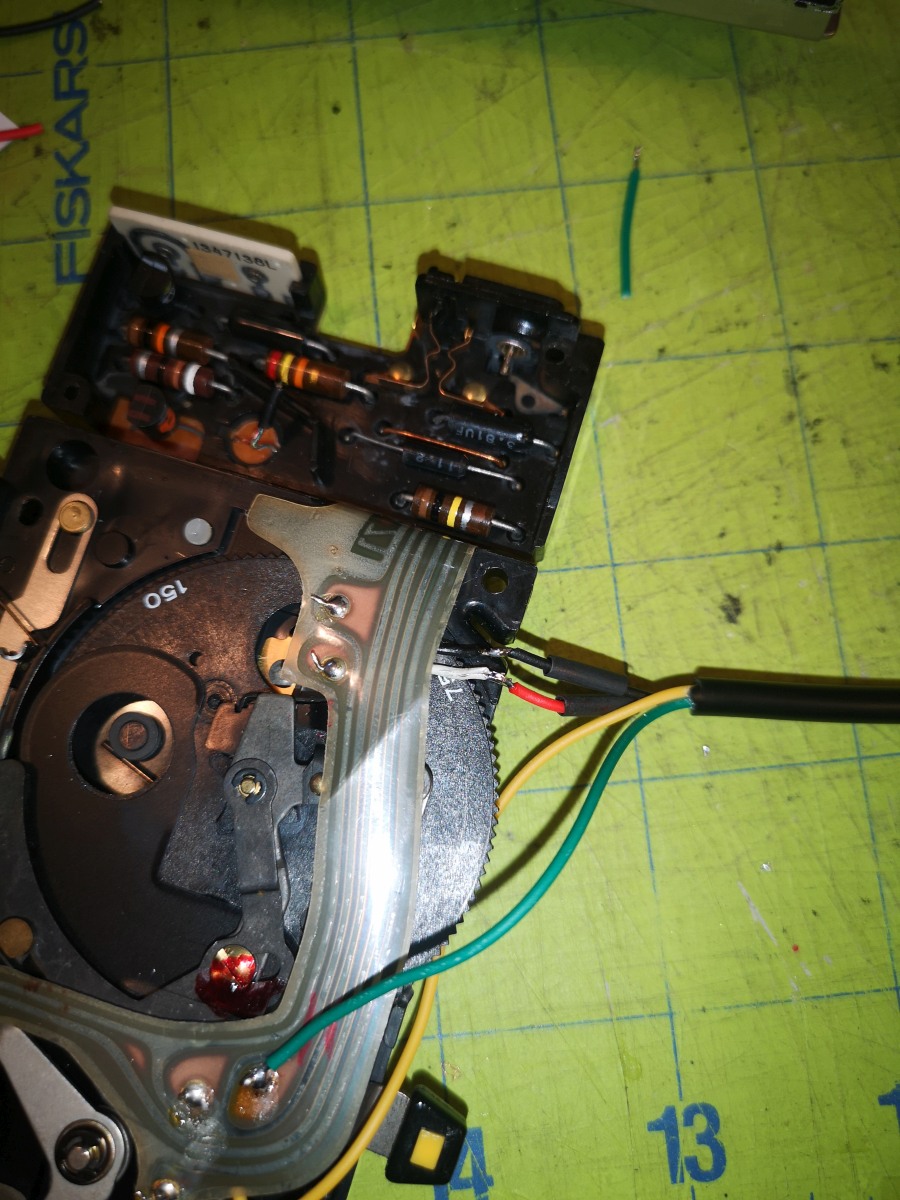
|
Apply heat to shrink the tubing, being careful not to melt the ribbon cable. | 
|
Tuck the wires into the groove which brings them to the rear of the shutter body. | 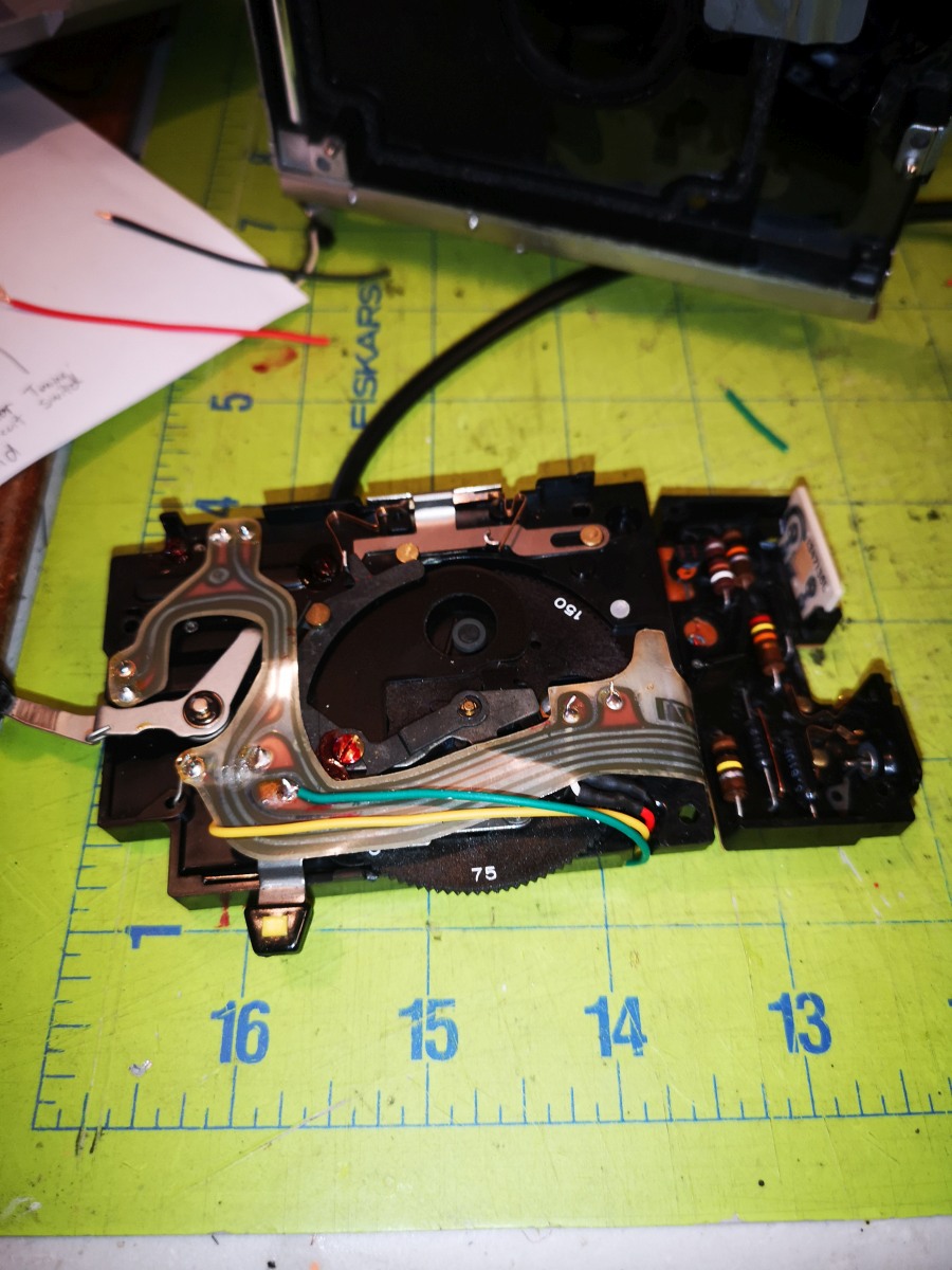
|
Clean the lens on the camera with a lint free cloth. | 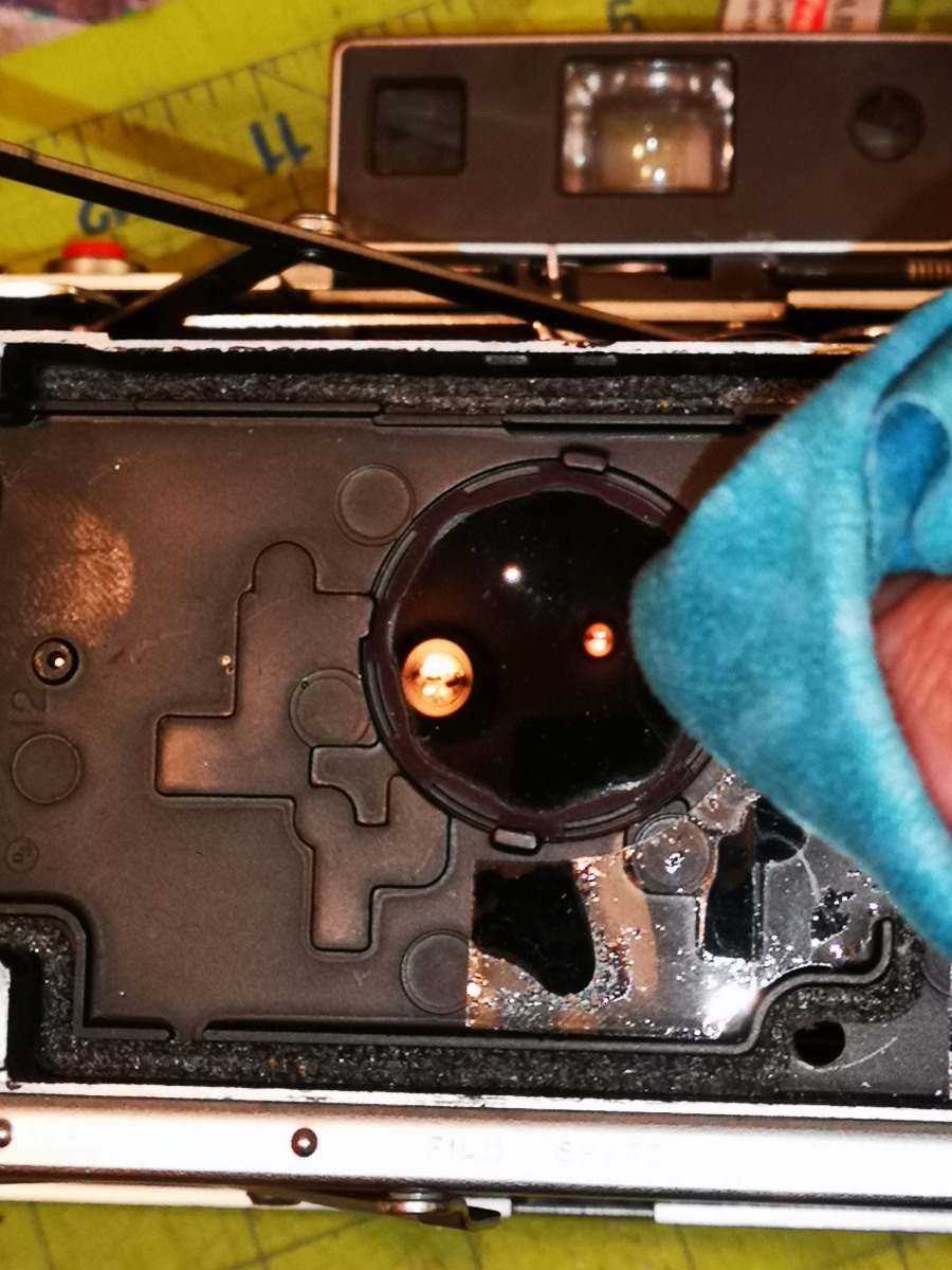
|
Clean the lens on the front of the lens body with a lint free cloth. | 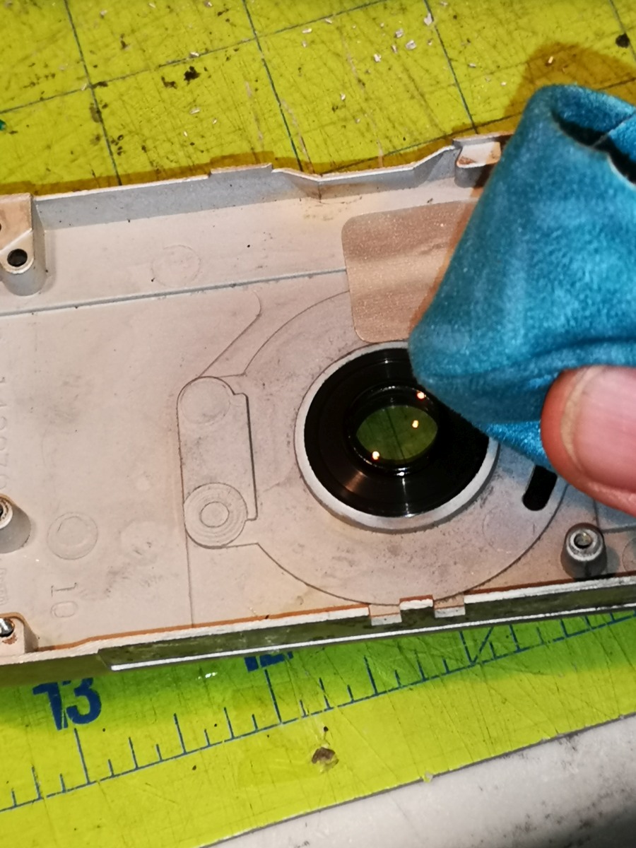
|
Flip the shutter body over and place into the front half of the lens body and screw down the two small screws holding the circuit board housing. | 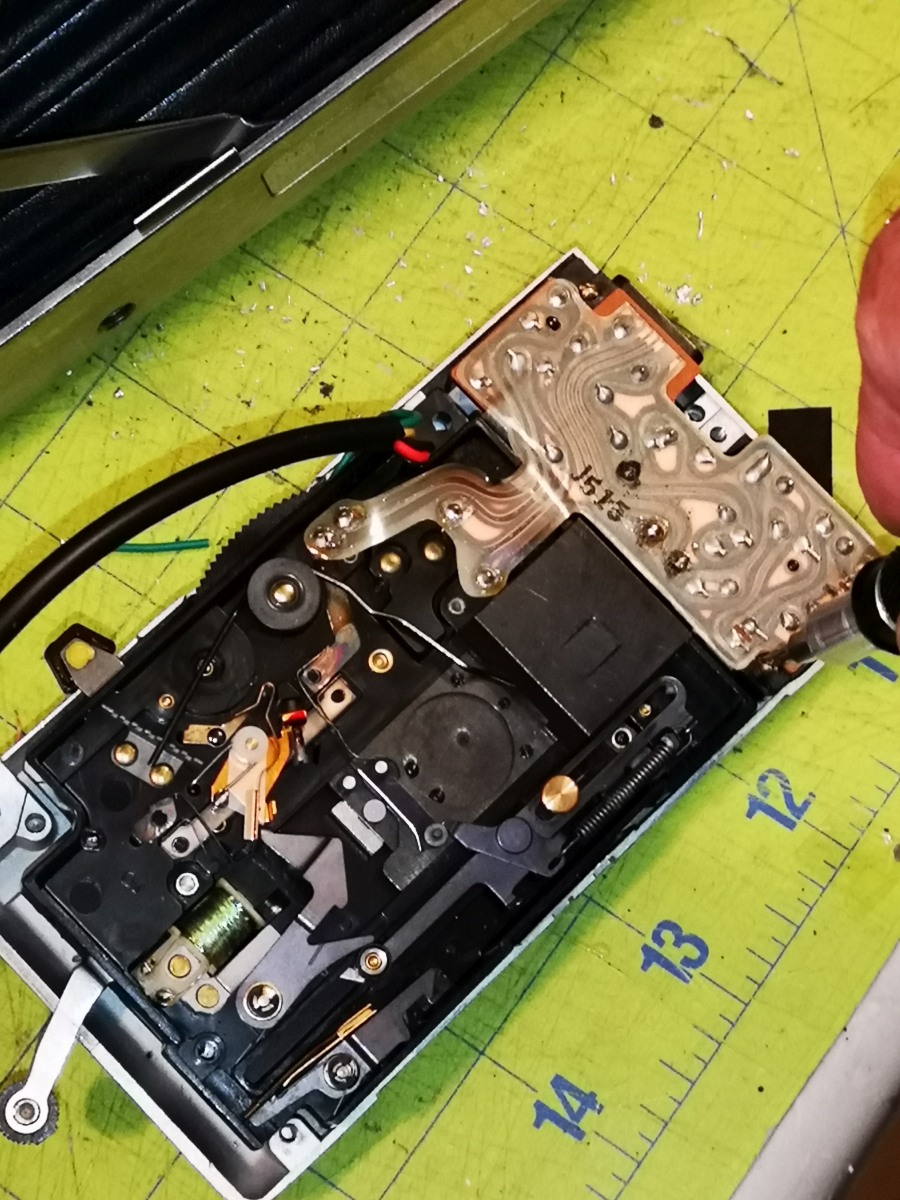
|
Insert the dark screw on the left side of the shutter body but don't torque it down fully so that you can line up the next screw easily. | 
|
While pulling down on the shutter cocking lever, insert the brass screw and torque it down, then torque down the dark screw to the left. | 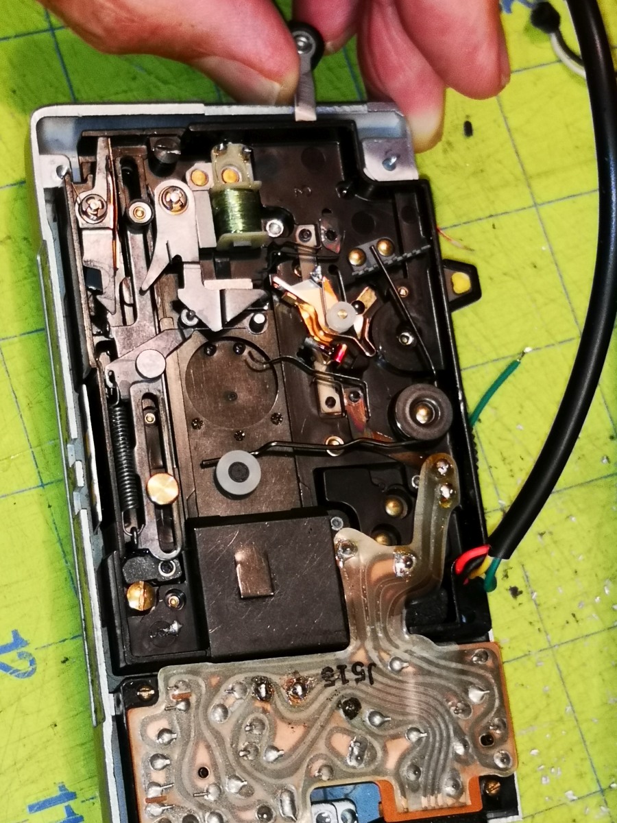
|
Run the 4 conductor cable through the hole in the back of the lens body. If the hole is too small, drill it out larger. | 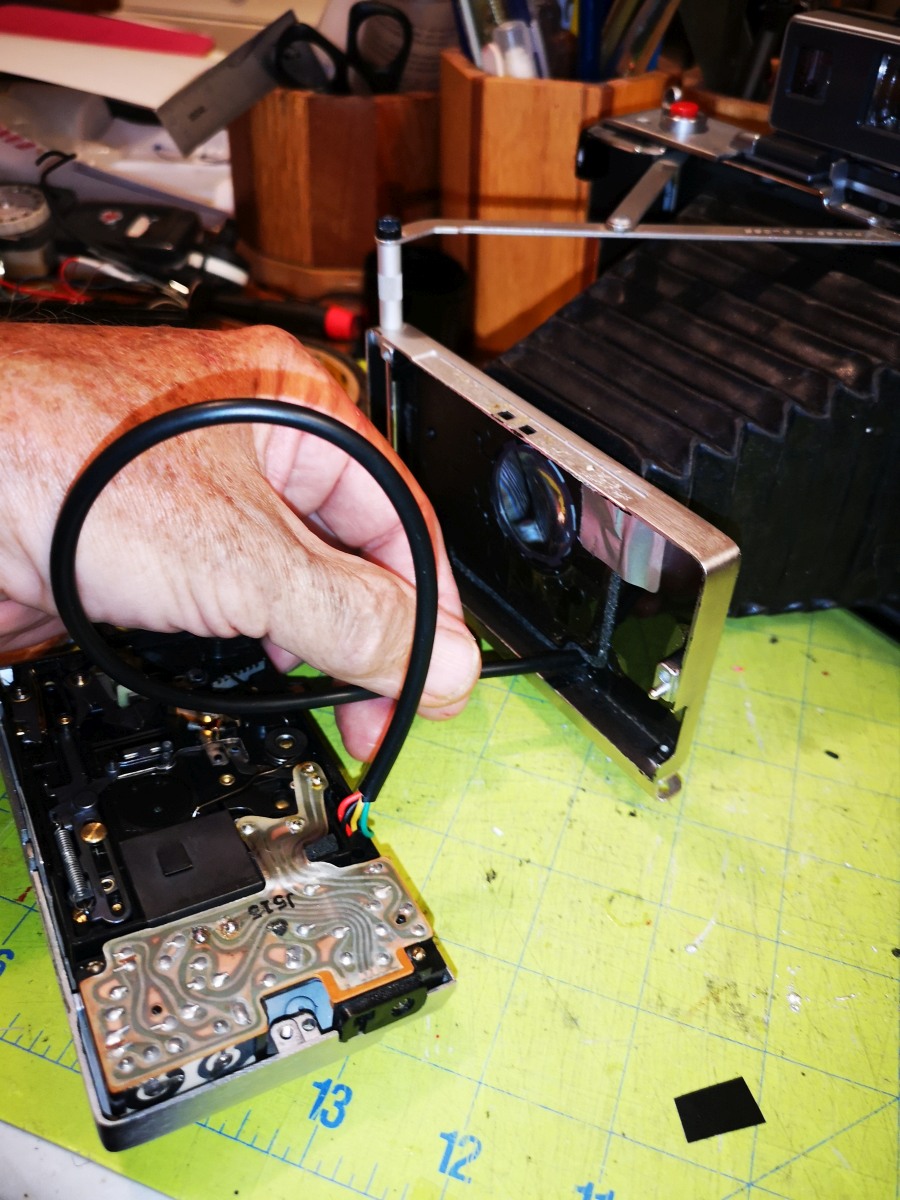
|
Place the light shield in the bottom left corner of the lens body, and bring the front half to the rear half of the lens body, pulling the cable through the hole as it comes together. Screw the lens body down with the 3 screws. | 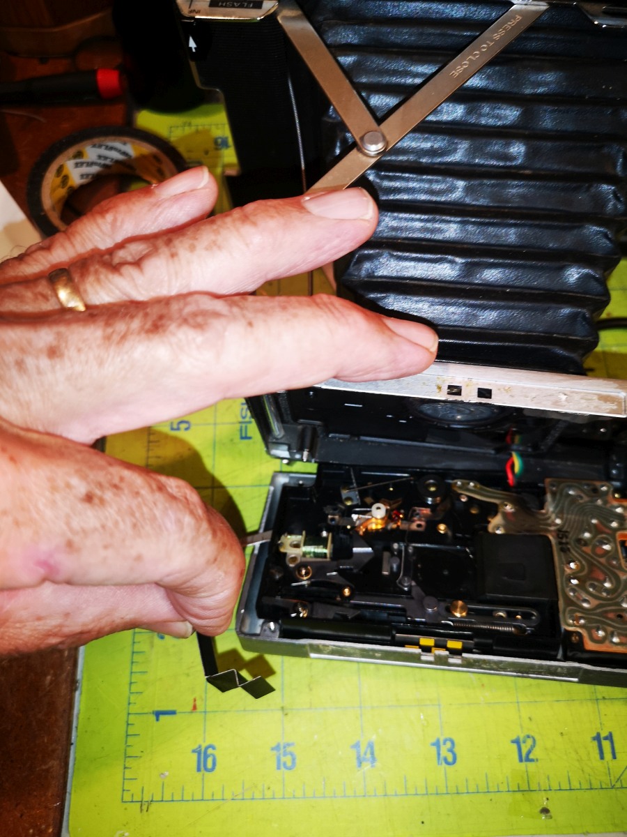
|
Run the 4 conductor cable in behind the grip through the hole that the old power cable ran. You may need to drill it out larger if it doesn't fit. | 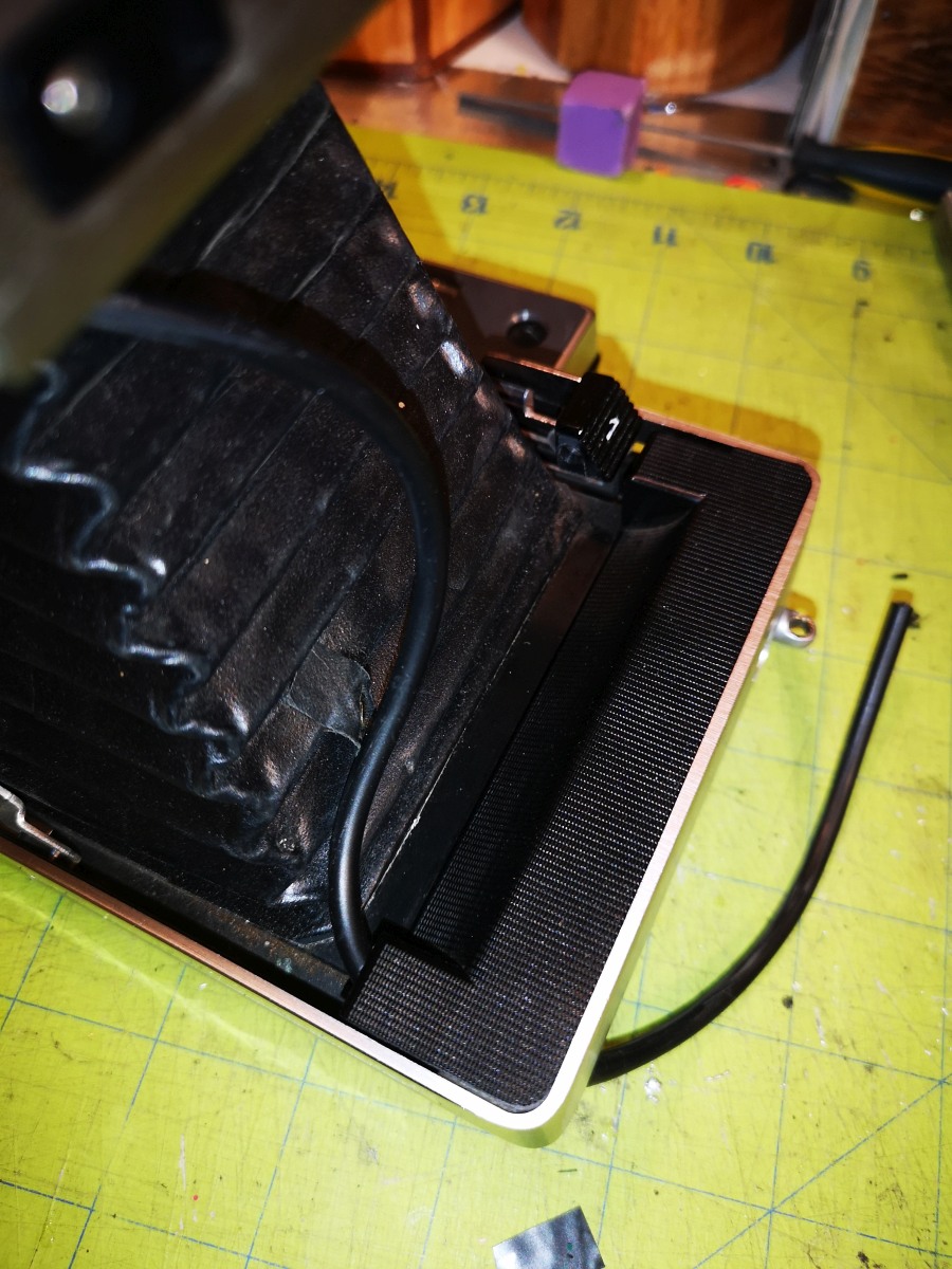
|
Mount the battery compartment onto the camera with a hinge pin, being sure to push it in until it engages the opposite side. | 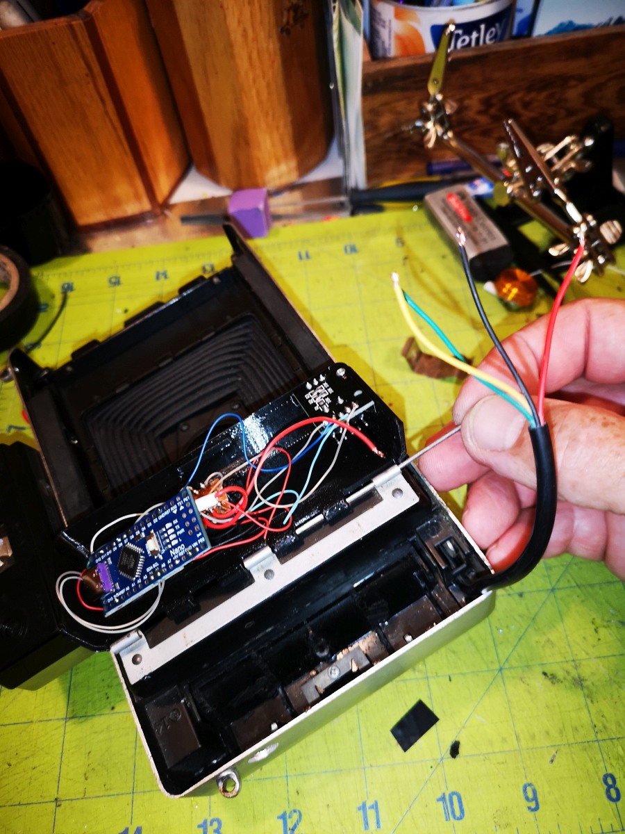
|
Strip and tin the tips of the 4 conductor cable. | 
|
Solder the shutter timing switch lead to the lower terminal of the middle switch. | 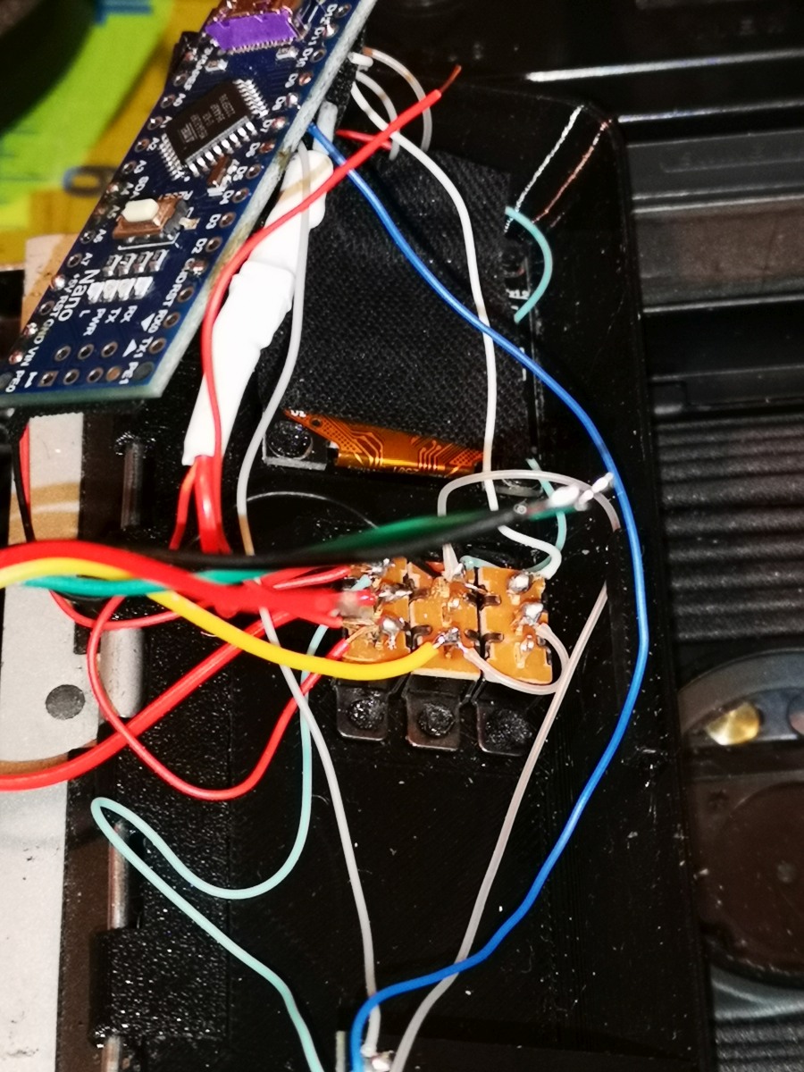
|
Solder the shutter circuit lead to the middle terminal of the middle switch. | 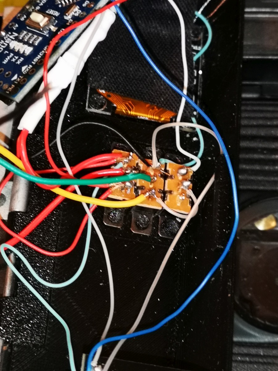
|
Solder the red lead of the 4 conductor cable to the lower terminal of the left switch. | 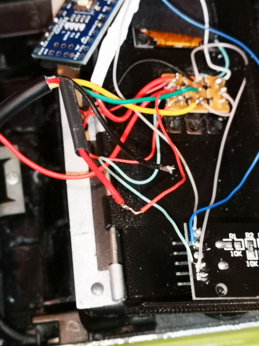
|
Solder the black lead from the 4 conductor cable to the lower terminal on the rotary controller, along with the negative terminal to the battery. Solder the positive terminal of the battery holder to the middle terminal of the left switch. | 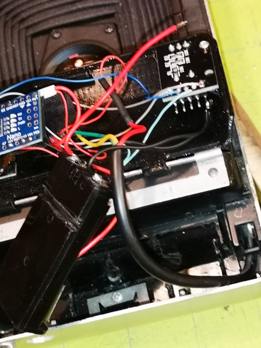
|
Place tape over the oLED display, switches, and rotary encoder to insulate them from other components, then line up the arduino and battery holder and carefully close the battery door. It's a tight fit and may need to be forced closed. | 
|
To use, switch all switches up for manual control. Dial the knob to select shutter speeds. Once you cock the shutter, the shutter speed cannot be changed as the arduino is waiting for the shutter to open and can't check the rotary encoder constantly if it's going to time the exposure accurately. If you want to uncock the lever, switch the two left switches down and press the shutter release. The shutter will fire with the closing curtain following immediately after the opening one.
You can shoot in automatic mode by switching all switches down. You can shoot in bulb mode by switching the left switches up and keeping the shutter button pressed down.
Once the code is uploaded and the Nano is connected to a display and switches, when you apply power it should start up and display the current shutter speed and be ready to control the shutter.
First, I came up with a shutter to resistance ratio with both the open and closed aperture settings. This is the "indoors" (open) vs "sunny day only" (closed) setting indicated above the lens:
| Resistance | Shutter speed | Resistors | accumulated resistors | total accumulated | |
|---|---|---|---|---|---|
| sOhms | Open | Closed | |||
| 379K | 2 | 3 | 33K+47K | ||
| 250K | 1 | 2 | 100K+100K | 100K | 248K |
| 160K | 1/2 | 1.3 | 100K+47K+10K | 47K | 148K |
| 100K | 1/4 | .8 | 100K | 39K | 101K |
| 55K | 1/8 | .44 | 47K+10K+10K | 33K | 62K |
| 30K | 1/15 | 1/4 | 33K | 15K | 29.4K |
| 15K | 1/30 | 1/8 | 15K | 6.8K | 14.4K |
| 7.5K | 1/60 | 1/15 | 6.8K | 3.9K | 7.6K |
| 3.75K | 1/125 | 1/30 | 3.9K | 1.9K | 3.7K |
| 1.875K | 1/250 | 1/60 | 1.9K | 1K | 1.9K |
| 938 | 1/500 | 1/125 | 470+470 | 470 | 926 |
| 468 | 1/1000 | 1/250 | 470 | 470 | 463 |
This table gives you 2 ways to build the array: one where each value is built by combining resistors, and the other where each accumulated value is the sum of all the ones before it. You'll notice the math doesn't add up. This is due to resistor tolerance. When building an array using accumulated values, you should build it on the fly, otherwise the accumulated value go off from the official resistor values. The advantage of building the array with accumulated values is that all the resistors fit under the 12 point switch, whereas the individual values stretch out to one side making the array quite a bit bigger.
Notice the values above 1/8 second are pretty much linear in their ratio. Below that, it departs from a linear relationship. I've tested this on the original model 100 and the model 450 and the values are the same.
| Diassemble the shutter body. This will involve 3 screws and removing the aluminum sticker indicating the aperture setting. Unscrew the shutter circuit from the back of the body. You may need to cock the shutter to get at one screw. Desolder the electric eye from the circuit board. The plastic covering on top will likely melt a bit so do this as quickly as possible. | 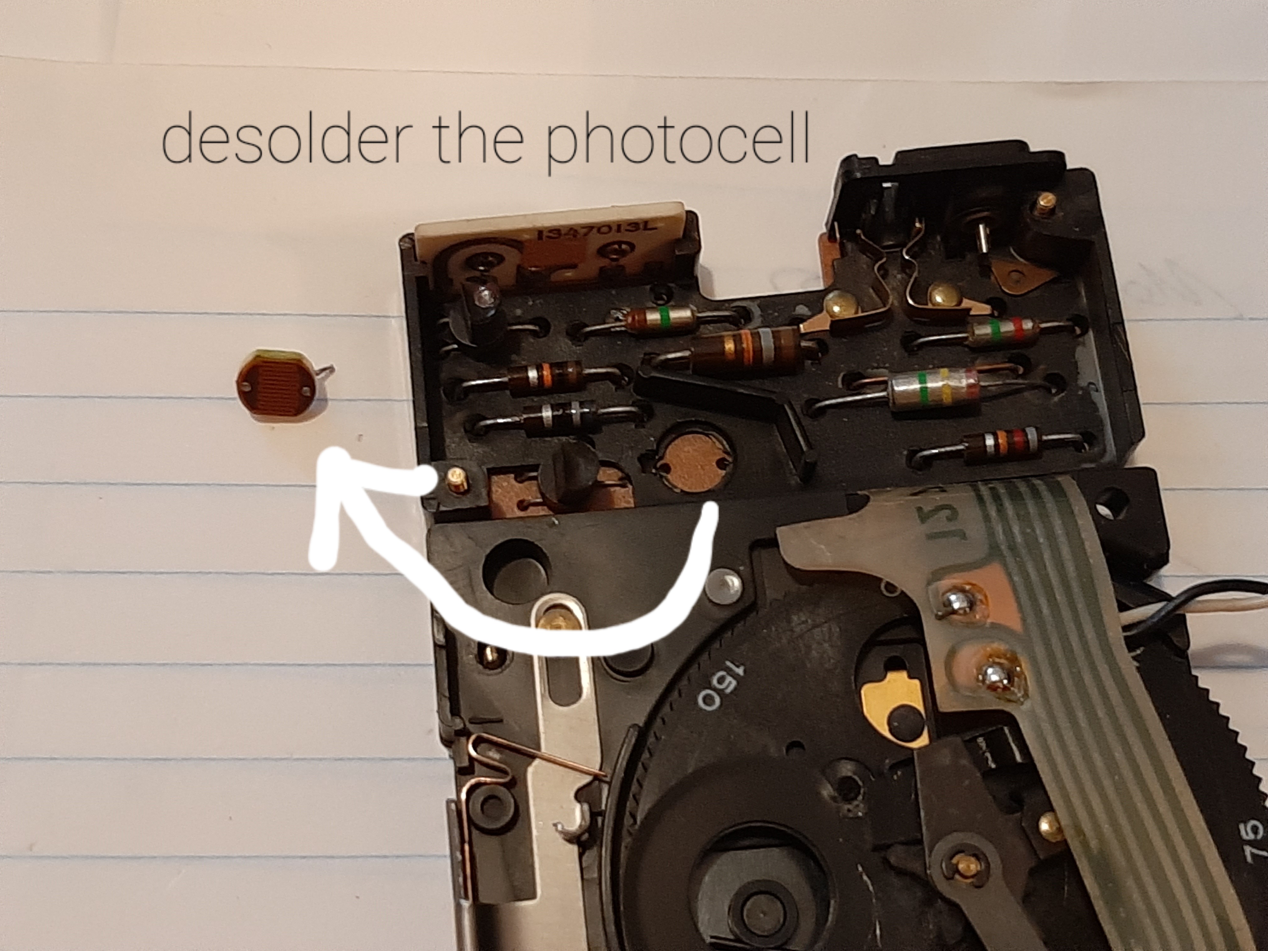
|
| If you don't want an automatic exposure option, solder some leads to the electric eye terminals, then jump down to Making the resistor array | 
|
| If you want to retain automatic exposure as an option, look at this wiring diagram to see how this circuit will eventually be wired. A switch will be used to choose between auto and manual exposure. | 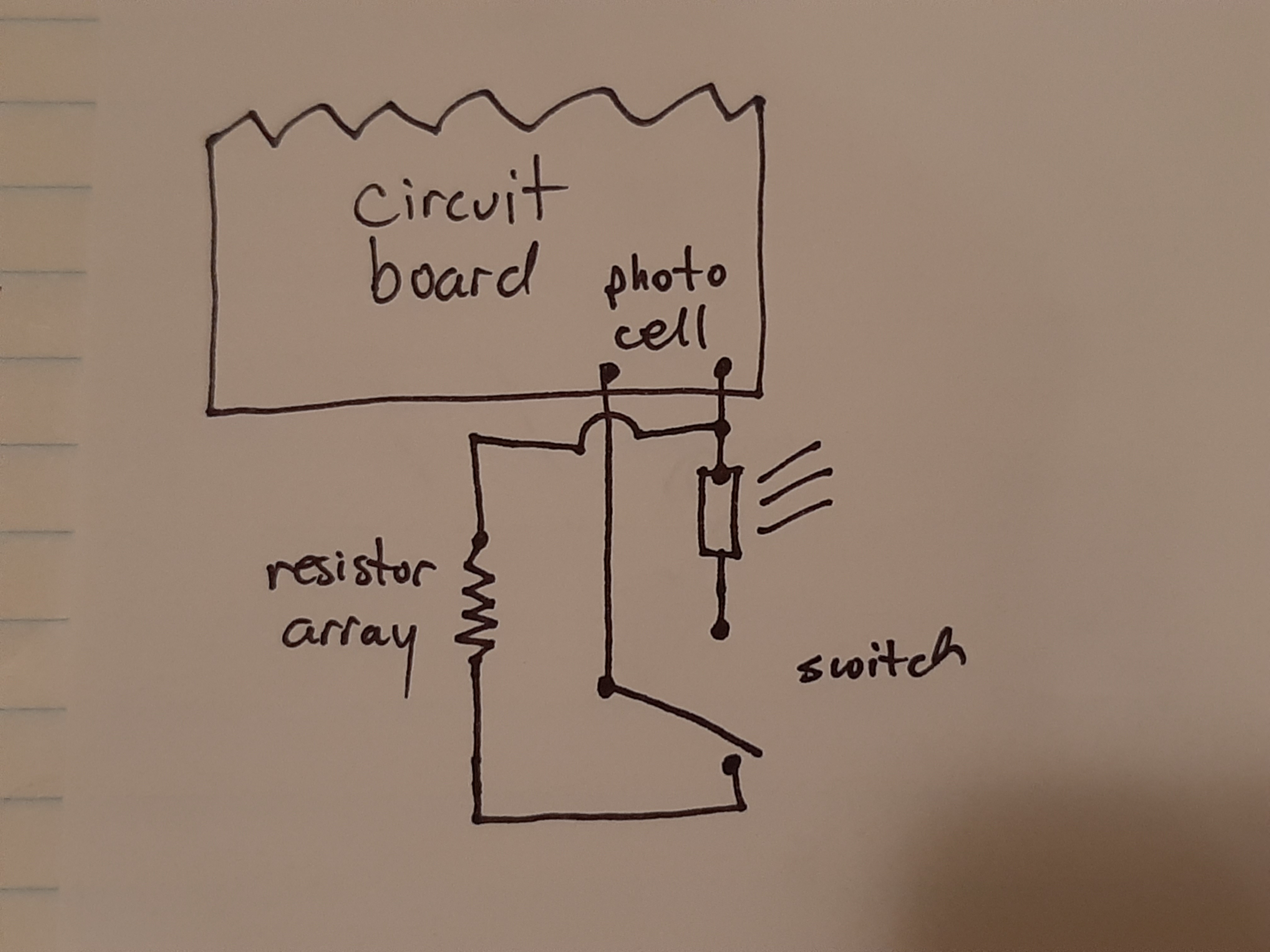
|
| Bend one of the terminals of the electric eye 90 degrees so it doesn't get soldered to the circuit board again, and attach a lead to it. | 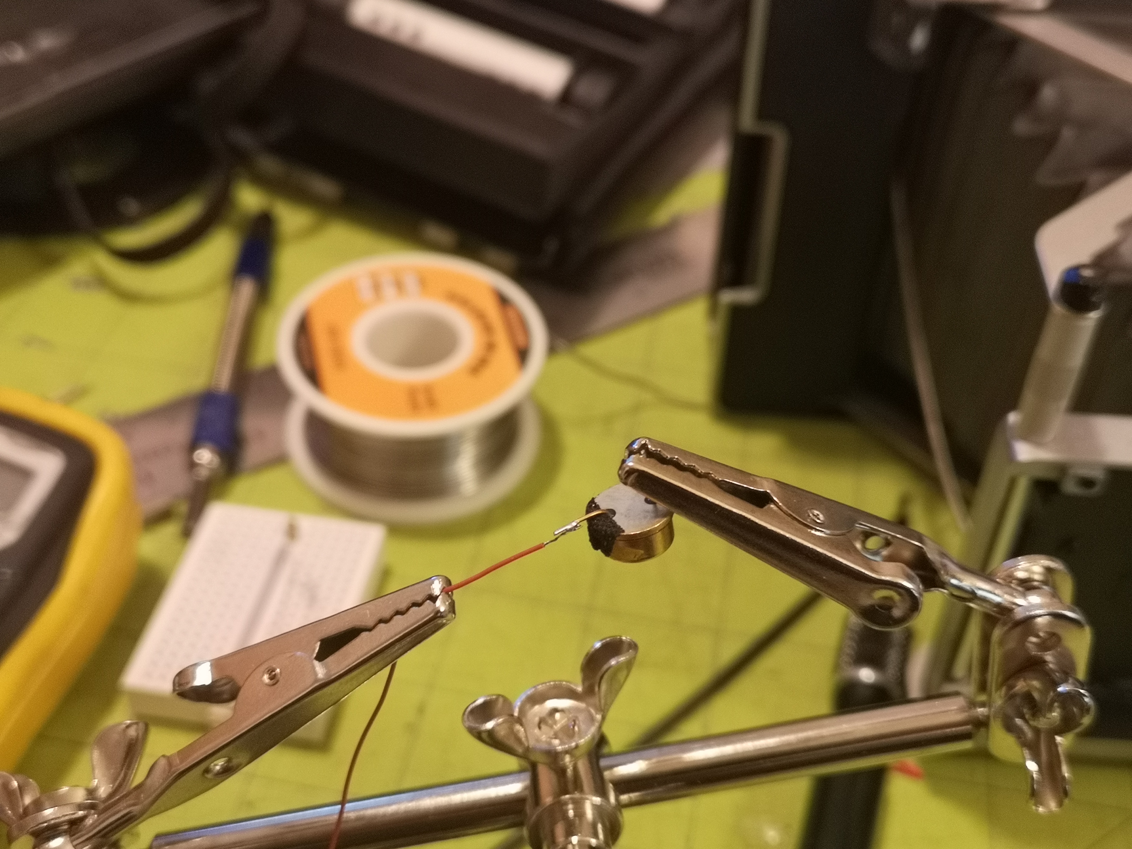
|
| Make a cut in the plastic that the electric eye sits in to make room for the 90 degree wire, then insert the electric eye into the circuit board and solder the unbent terminal and one of the leads to the circuit board, and another lead to the empty terminal on the circuit board. You should have 3 wires coming from the shutter circuit. | 
|
| Using the above table, solder the accumulated value for each resistor(s) in series, connecting one switch terminal to the next in a cascading manner. Start with a 470 ohm resistor, soldering it to terminal 12, leaving the other end of the resistor free to solder to the lead to the electric eye. The accumulated value will be the sum of all the resistors in series, depending on the position of the switch. Because of this, you just need to solder the leads from the electric eye to the middle terminal and the resistor soldered to the 1/1000 sec terminal of the rotary switch. | 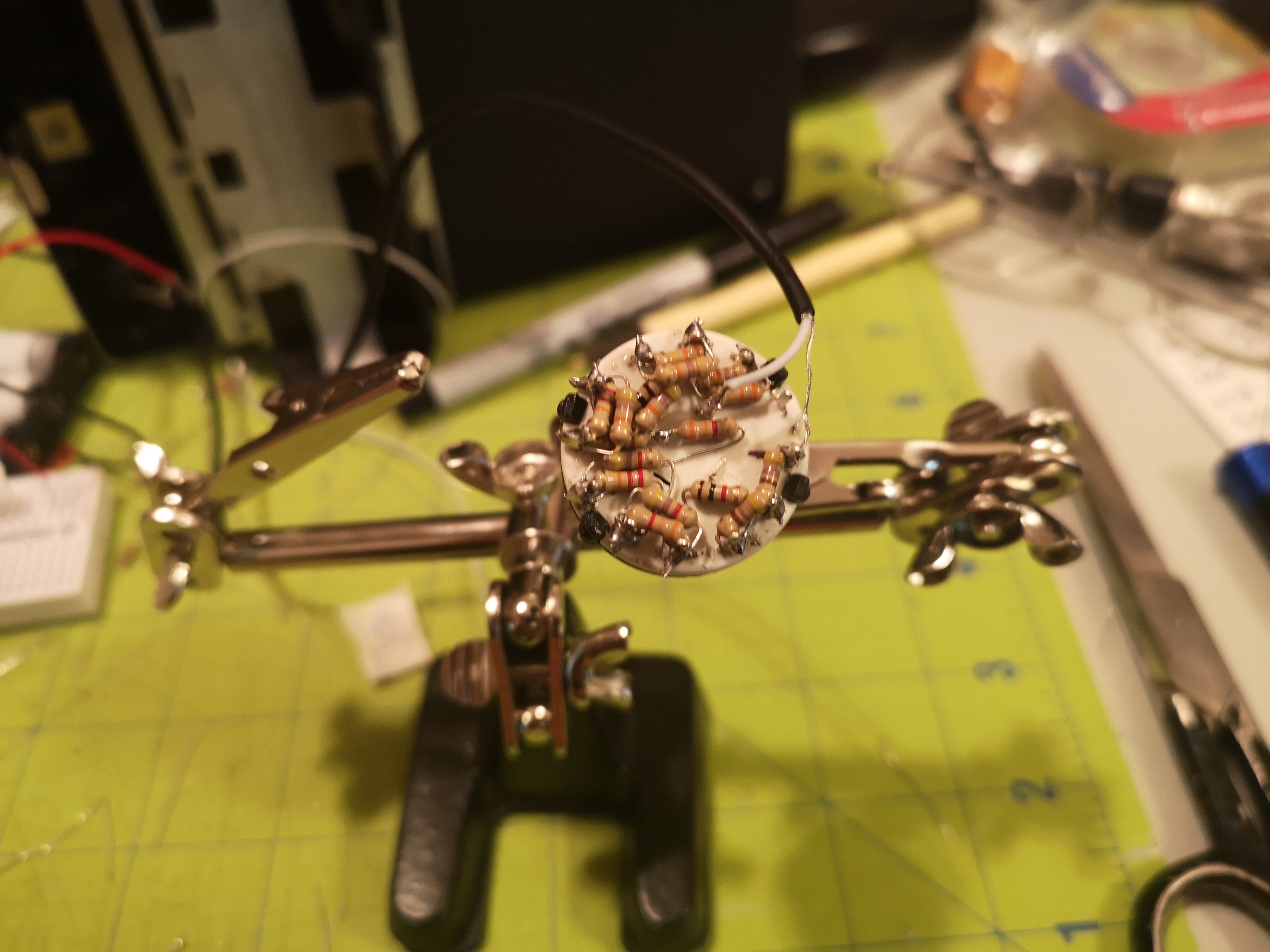
|
| If you would rather build the array with individual values for each switch point, solder the appropriate resistors to each terminal of a 12 point single pole switch. You'll likely need to combine values to reach the necessary value. | 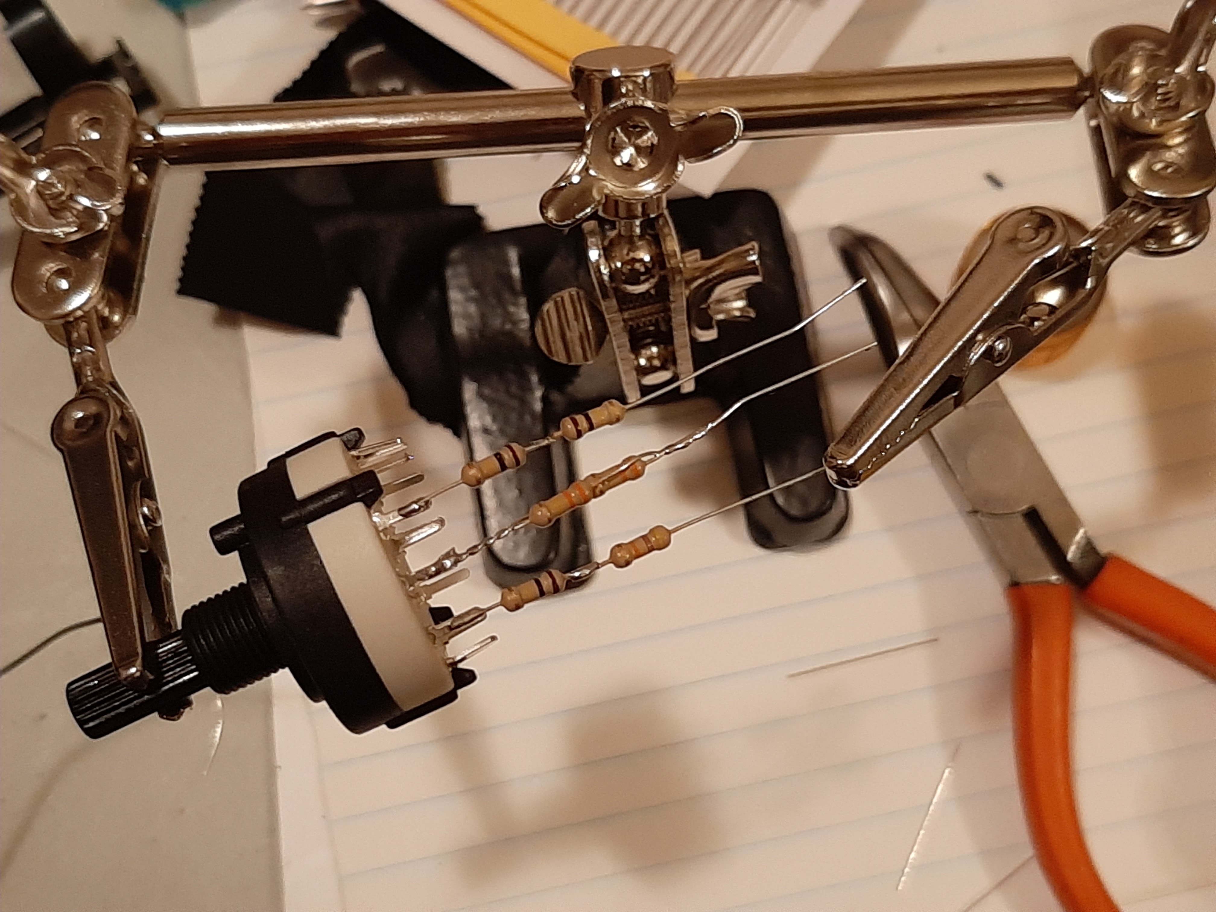
|
| Cover each line with heat shrink tubing to prevent any shorts. This was the way I did my first 2 manual conversions, but having done an array in series, I would recommend that method. | 
|
| Fold the resistors 90 degrees and solder all the leads together. This will connect to one of the leads which goes to the electric eye terminal. Connect the other lead from the other electric eye terminal to the middle terminal on the sliding switch. Then, connect the lead from the electric eye on one end of the switch and the resistor array to the other. This will allow you to switch back and forth between manual and automatic shutter. | 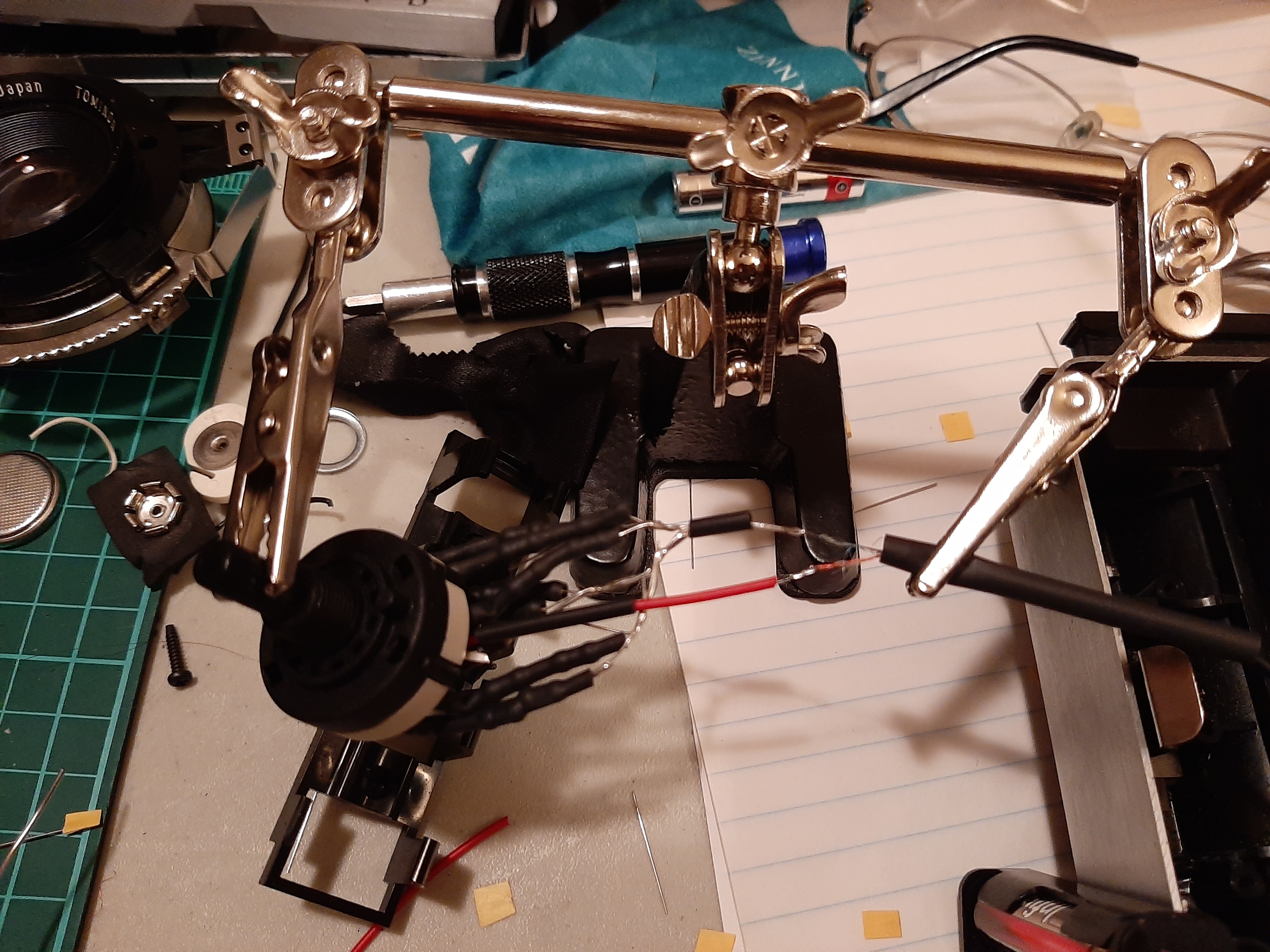
|
| I would test the array before putting everything back together. Test the 1/2 second and compare it to a known good shutter. If it is slow or fast, you can adjust it by moving the trim POT on the side of the shutter circuit. The POT at the top of the camera seems to fine adjust the timing. Counterclockwise makes the shutter slower, and clockwise makes it faster. | 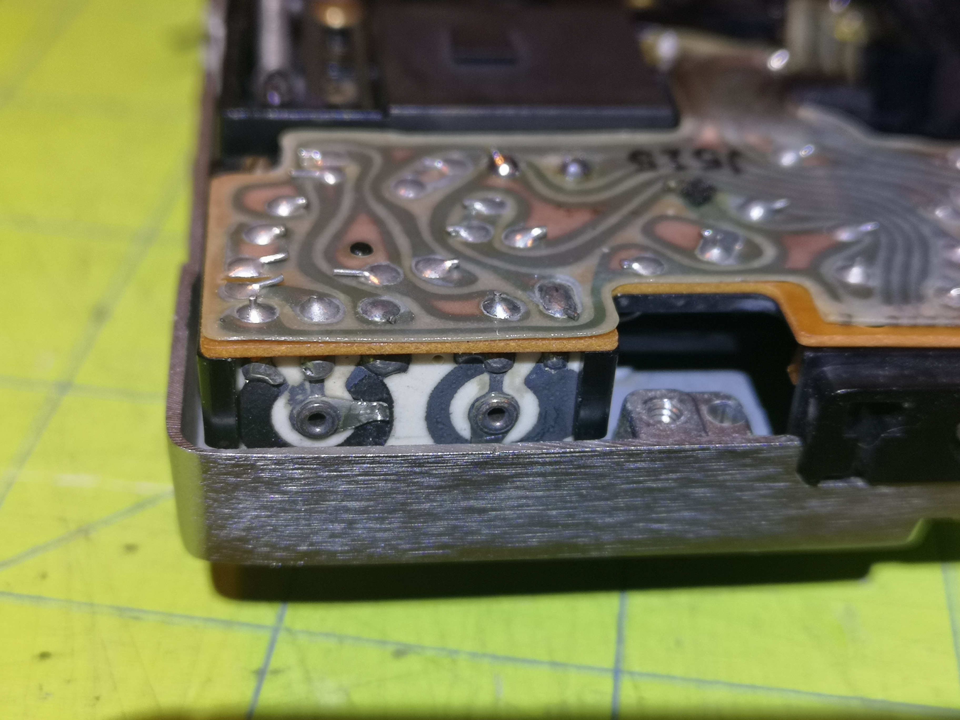
|
You have two choices in going forward: You can use a plug in resistor array dongle (which can be used for multiple cameras), or you can hard wire the resistor array into the camera.
Use this method if you want manual shutter control to be an add-on to the camera. One resistor array can be used with multiple cameras. The camera operates in automatic exposure mode by default. When you plug in the resistor array, the camera uses that for manual shutter control. The array "dongle" slides into the flash mount. Files for the dongle can be downloaded here
| Cut the plastic shroud at the top of the circuit wide enough for a 2.5mm jack. Line up the lens body with the circuit board and mark where the 2.5mm jack hole should be drilled, then drill a hole for the jack. | 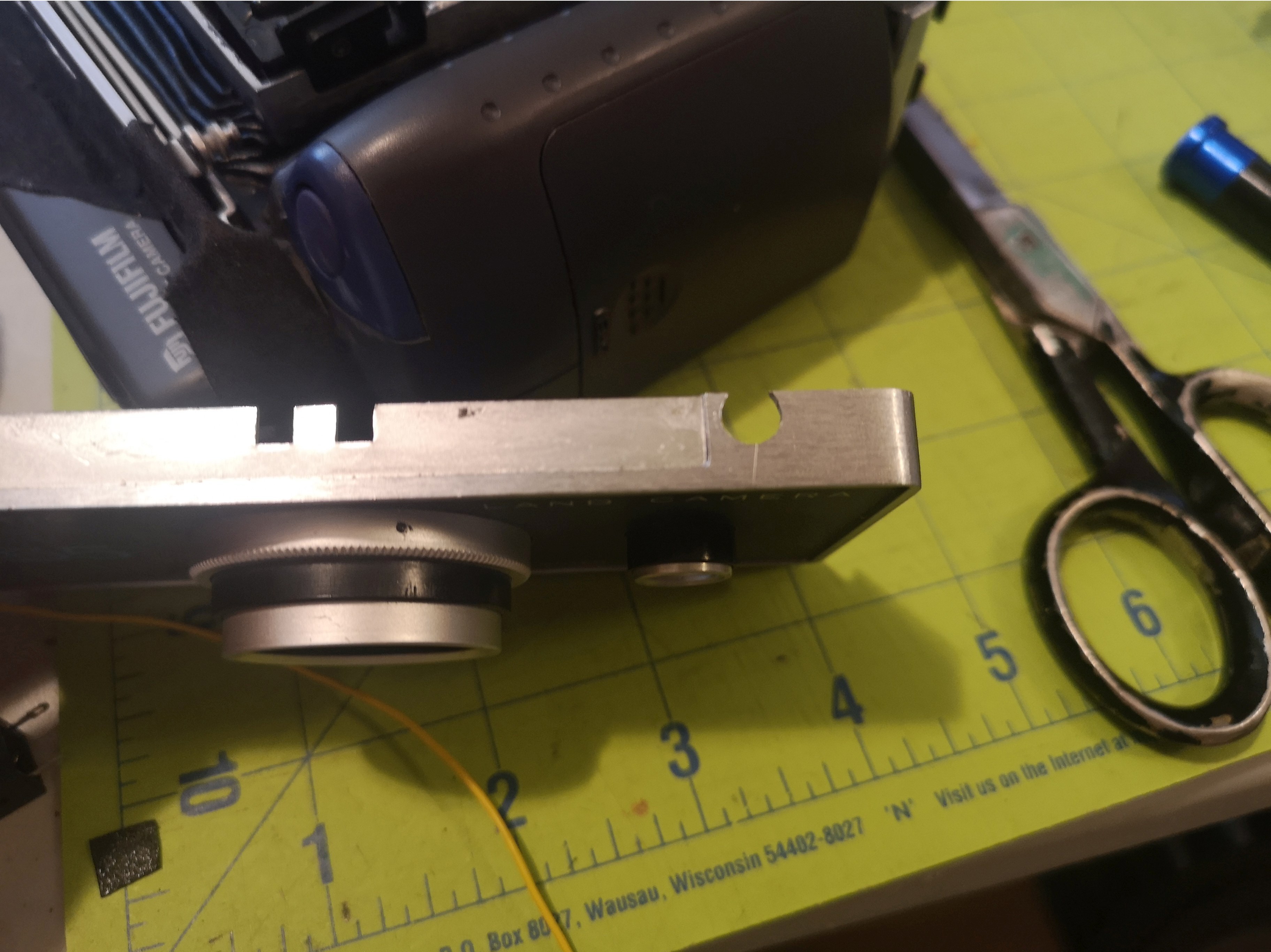
|
| Solder the leads coming from the circuit board to the 2.5mm jack: The lead coming from the electric eye gets soldered to the switch terminal, the lead from the circuit board that the electric eye did not get soldered to gets soldered to the tip terminal (which is a closed circuit with the prior lead when no jack is inserted), and the lead from the circuit board that the electric is IS soldered to gets soldered to the barrel lead (usually on the side of the jack). | 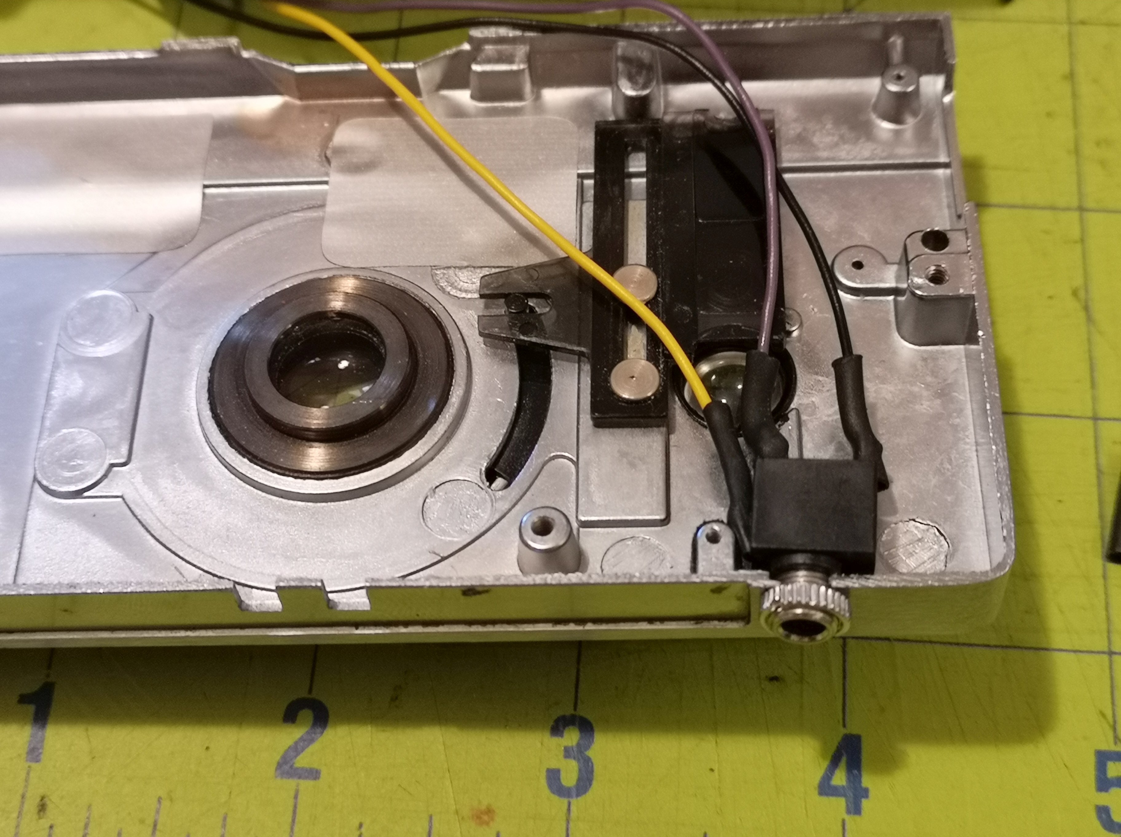
|
| Install the jack into the drilled hole and assemble the lens body. Before screwing everything together, verify that automatic exposure works without a jack plugged in. Then, plug in a 2.5mm plug and verify that the shutter is on bulb mode (shutter stays open as long as you press the shutter). | 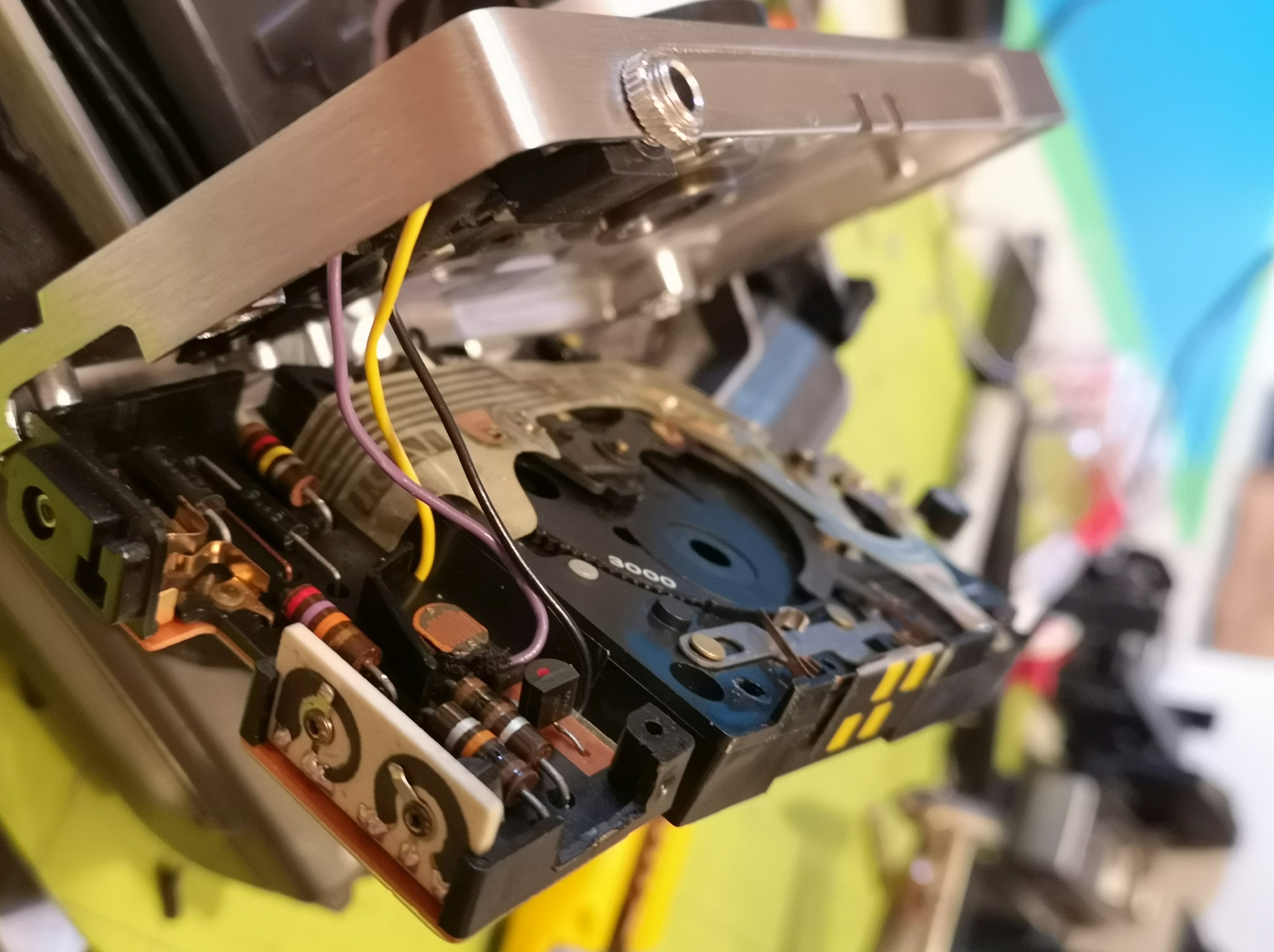
|
| Print up the resistor array box and mount found here. 400 series files are for 400 series cameras. Install the array into the box and glue on the bottom, feeding the leads out the edge hole. | 
|
| Here's the finished dongle attached to a 400 series camera. | 
|
This method can be used for a one off installation of the resistor array. If this is the only camera you are going to be installing the array into, or if you want to ensure you'll always have the capabilities of manual shutter control with your camera, this is a good method. Two holes will need to be drilled into the camera back/body: one for the array knob, and the other for the auto/manual switch.
| Run the wire along the battery cable to the battery compartment. | 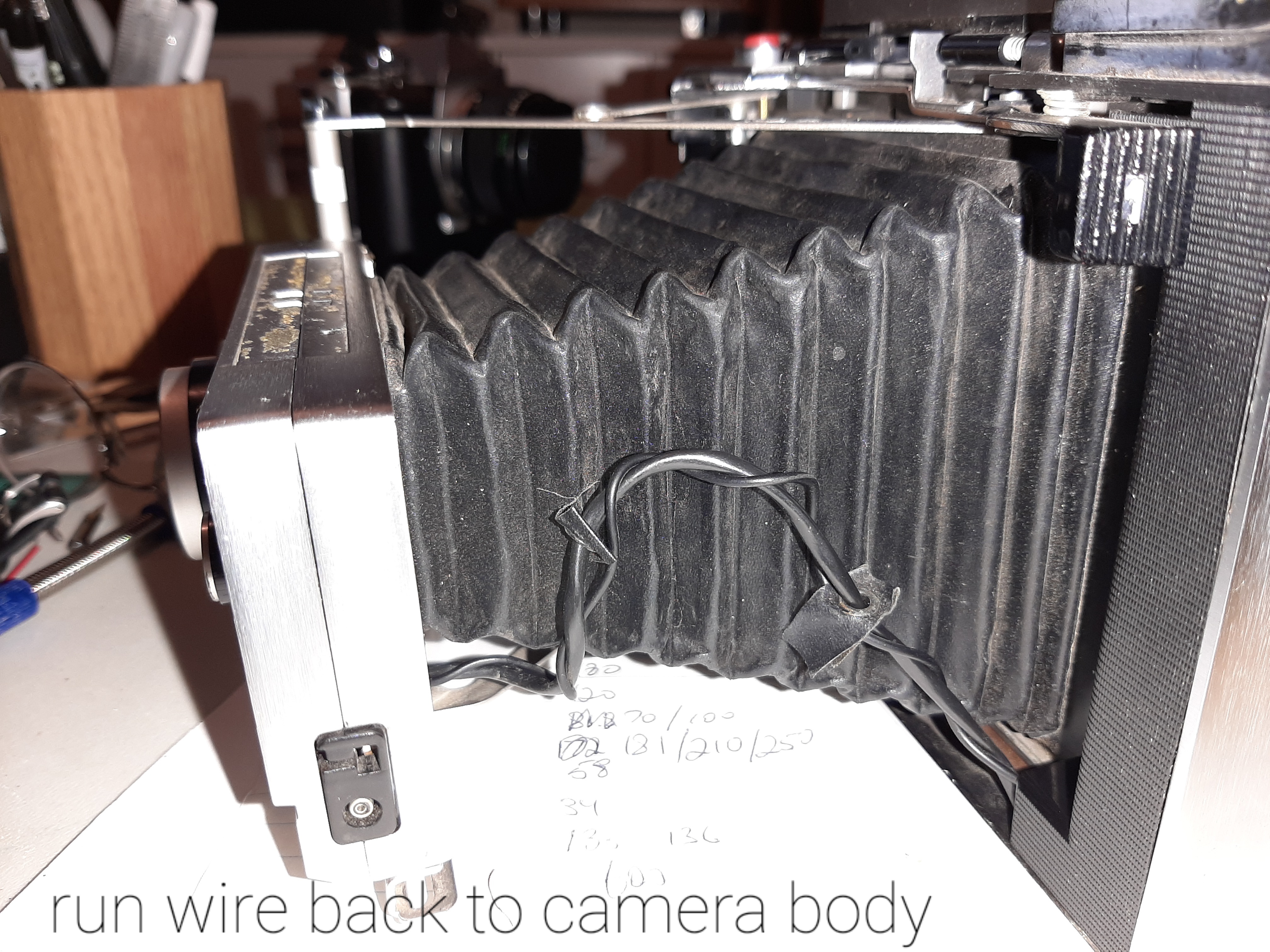
| |||||||||||||||||
| Pull the wires to the top of the battery compartment. You'll have 3 leads: two for the electric eye, and the other to switch between using the electric eye or the resistor array. | 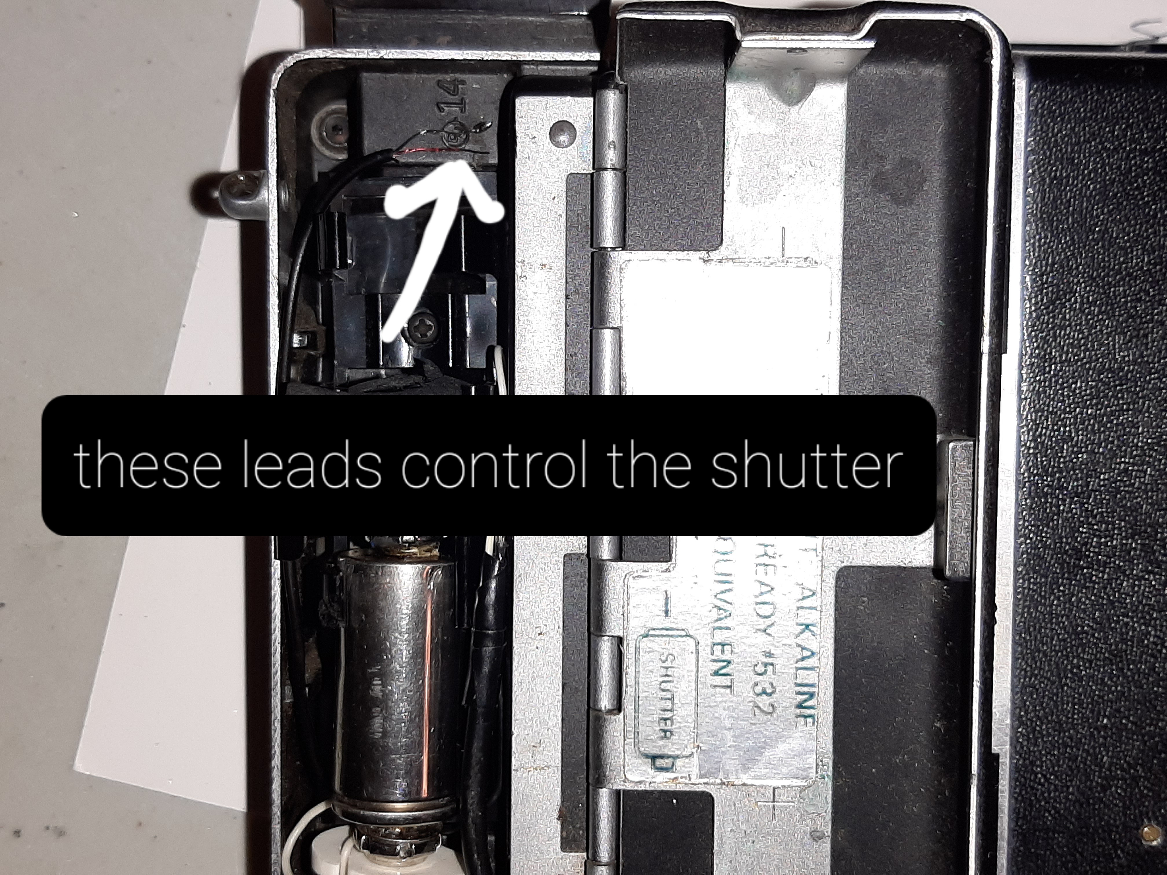
| |||||||||||||||||
| I mounted the rotary switch on the side of the camera which allows it to stay in place when opening the battery door. Drill a hole and insert the rotary switch shaft. | 
| |||||||||||||||||
| Make a shutter speed indicator and mount it, then screw the swtich in. This particular manual shutter speed control gives the camera shutter speeds in 1/2 steps under 1/60, for shooting paper negatives. A 12 point switch should give you 1/1000 sec to 1 sec and bulb for a normal camera. | 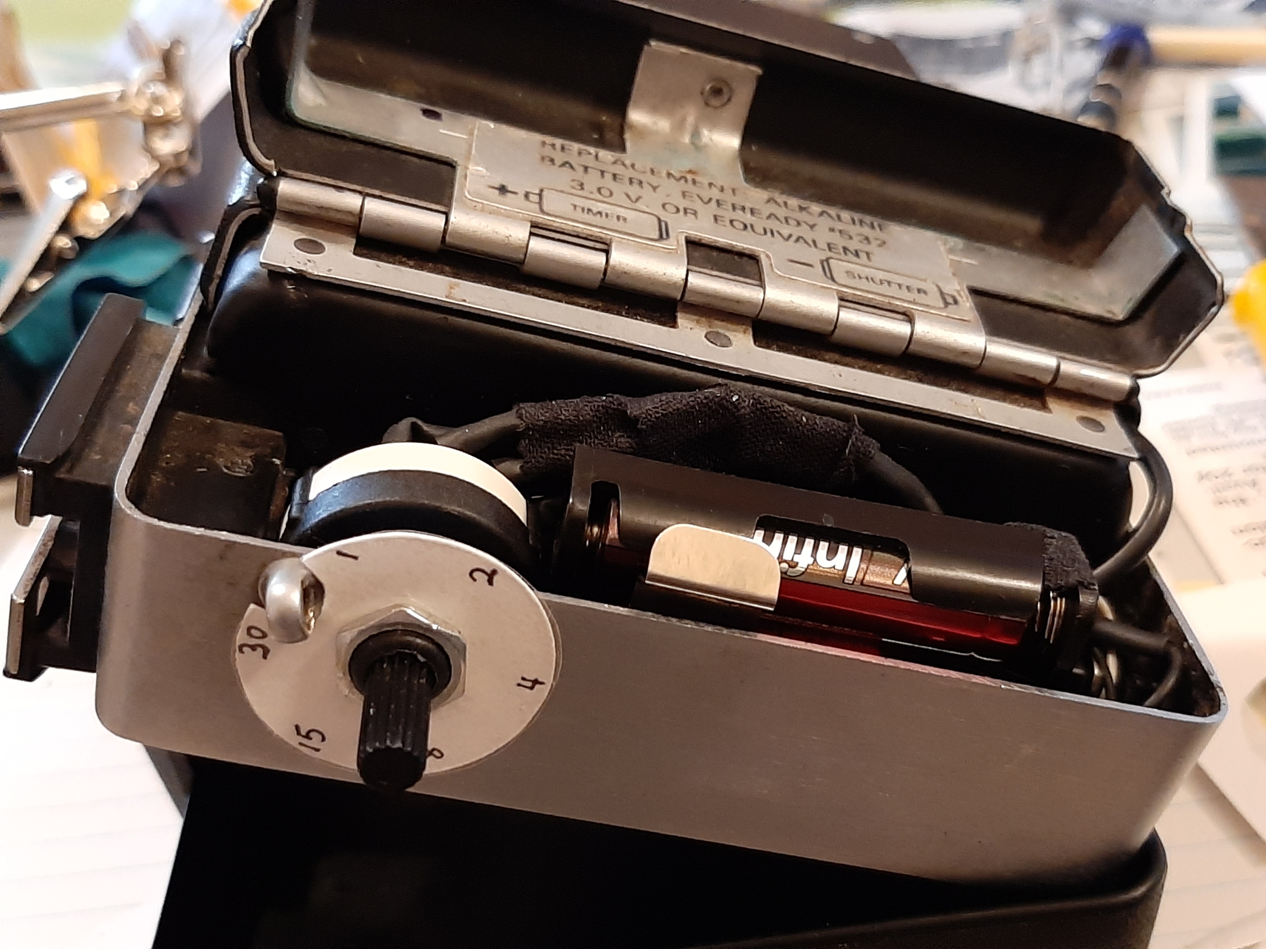
| |||||||||||||||||
| Here's the finished paper negative camera. I scribbled an aperture scale reminding me of the apertures on the different settings and ASA speeds. When the aperture is in the closed position, I need to decrease the shutter speed by 2 stops. Under 1/4 second I have to look up the shutter speed on a table. Here's a table with aperture values vs ASA/open/closed settings: | 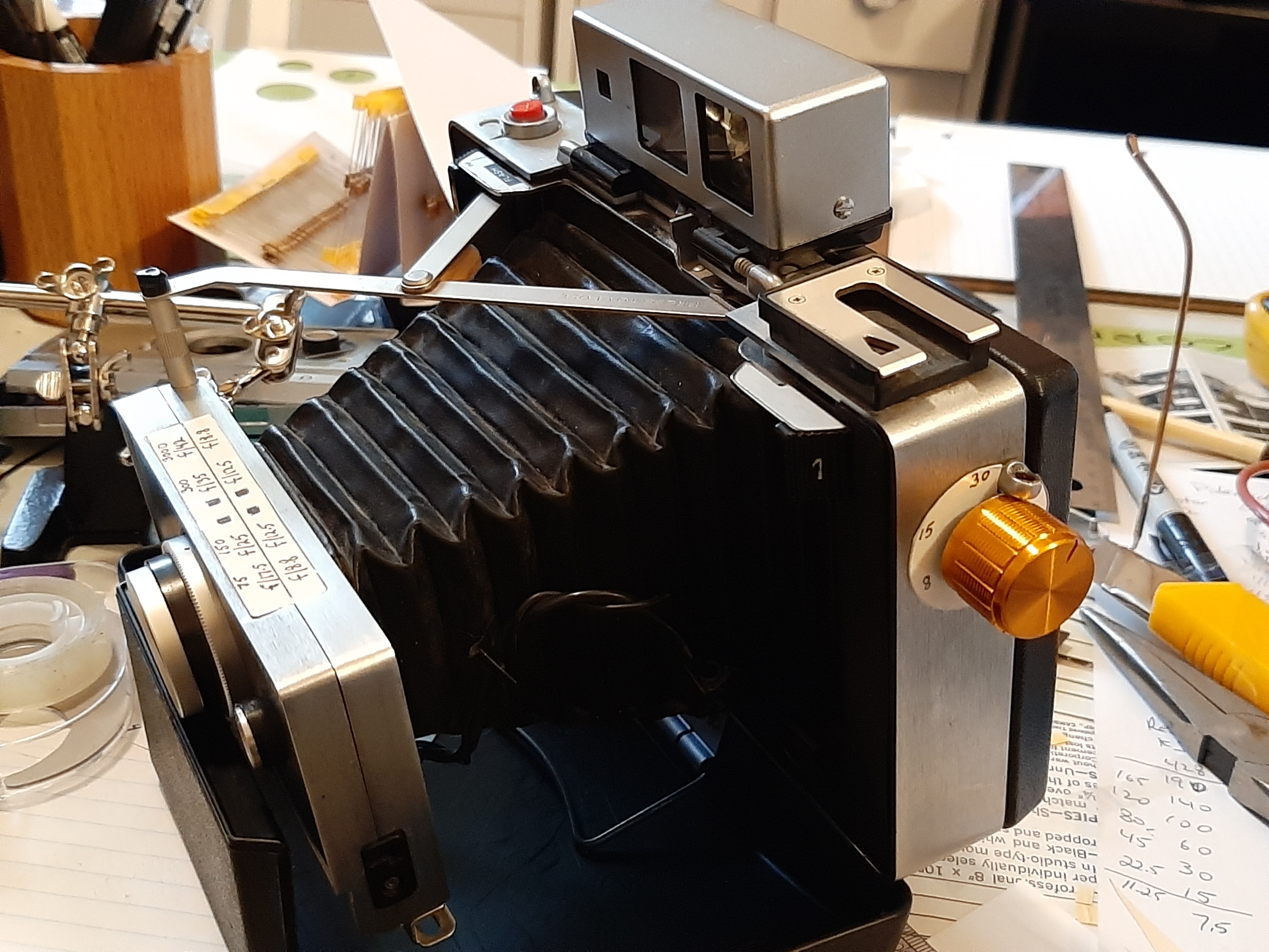
| |||||||||||||||||
| ||||||||||||||||||
| When using the closed settings, the shutter speed is 2 stops slower, so for instance, 1/125 with the open setting will be 1/30 with the closed setting. | ||||||||||||||||||
| ||||||||||||||||||
| The closed setting will shoot 2 stops slower like with the model 350/450. Additionally, with the open setting, ASA 150 and 300 will shoot 1 stop faster than the shutter speed indicated. Best to avoid those settings and just use f/8.8 with ASA 75, then use the closed settings with an additional 2 stops. | ||||||||||||||||||
| I made labels that can be printed, laminated, then trimmed to size and glued onto the lens body to remind you what aperture you're working with. There are 3 labels: one for models 100, 230, 240, and 250, one for models 340 and 350, and another for models 360, 440, 450, and 455. You can get them here | 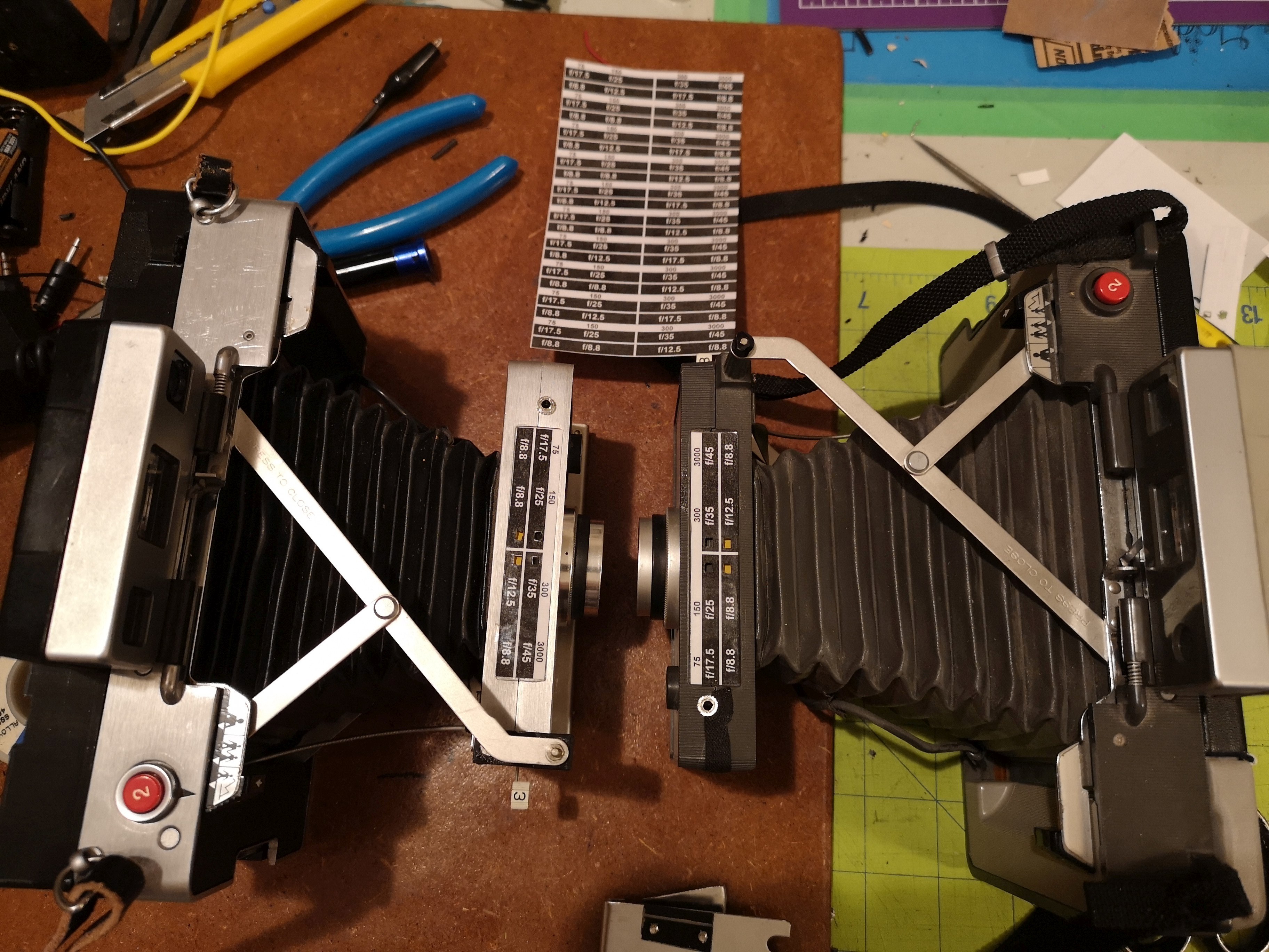
| |||||||||||||||||
| Here's a finished hardwired camera with speeds from bulb to 1/1000 sec. | 
| |||||||||||||||||
Feel free to contact me with any questions or news about your build!